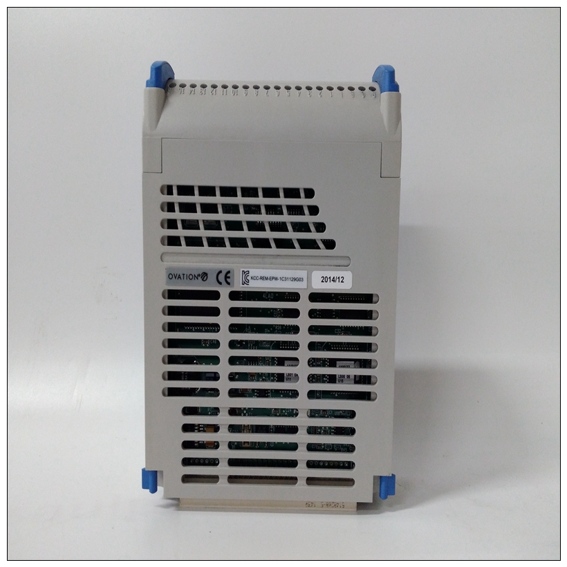
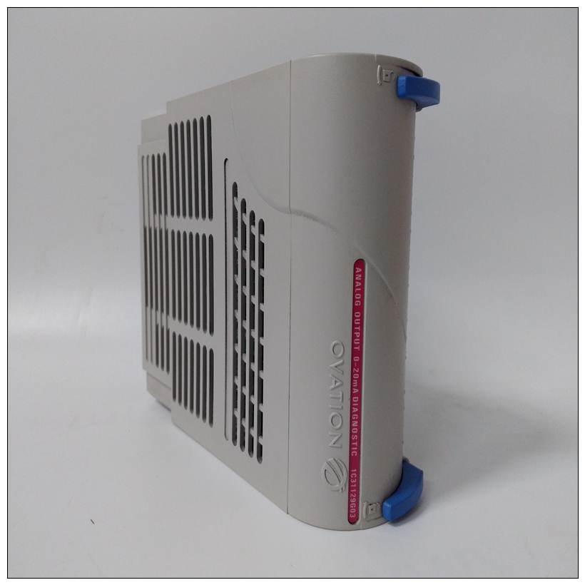
1C31129G03功率模块,EMERSON配置说明
正常地址范围响应正常地址的设备的内存映射范围如下表所示。正常地址范围为由本地总线上的传输类型(TT)信号定义。上MVME177,传输类型0、1和2定义正常地址范围表3-1。本地总线内存映射,是从$00000000开始的整个映射到$FFFFFF。地图的许多区域是用户可编程的,并且建议的用途如表所示。


1C31129G03功率模块缓存抑制功能为可在MMU中编程。车载输入/输出空间必须标记缓存禁止并在其页表中序列化。第3-6页的表3-2进一步定义了本地输入/输出的映射设备。1.Flash/EPROM设备的价格为$FF800000至$FFBFFFFF,如果ROM0位在VMEchip2 EPROM控制寄存器为高电平(ROM0=1)。这个ROM0位位于地址$FFF40030位20。ROM0设置为1每次重置后。必须先清除ROM0位,然后再清除其他位可以在此范围内映射资源(DRAM或SRAM)($00000000至$003FFFFF)。VMEchip2和DRAM映射解码器被本地总线重置禁用。MVME177上,闪存/EPROM内存映射为硬件默认情况下,通过VMEchip2.2。该区域可由用户编程。建议使用如所示桌子。DRAM解码器在MCECC芯片中编程,本地到VMEbus解码器在VMEchip2。3、尺寸为近似值。4.缓存抑制取决于映射区域中的设备。5、该区域未解码。如果访问了这些位置本地总线计时器启用,循环超时,并通过以下方式终止茶的信号。SRAM在MVME177上有可选的备用电池。下表重点介绍了本地总线主内存映射。有关寄存器位的完整描述,请参阅数据特定芯片的表。有关更详细的内存映射,请参阅到以下详细的外围设备内存映射。应使用字节读取来读取中断向量。这些当中断未挂起时,位置不响应。如果总线计时器已启用,访问超时并终止TEA信号。
Normal Address Range
The memory map of devices that respond to the normal address
range is shown in the following tables. The normal address range is
defined by the Transfer Type (TT) signals on the local bus. On the
MVME177, Transfer Types 0, 1, and 2 define the normal address
range.
Table 3-1. Local Bus Memory Map, is the entire map from $00000000
to $FFFFFFFF. Many areas of the map are user-programmable, and
suggested uses are shown in the table. The cache inhibit function is
programmable in the MMUs. The onboard I/O space must be
marked cache inhibit and serialized in its page table.
Table 3-2 on page 3-6 further defines the map for the local I/O
devices.1. Flash/EPROM devices appear at $FF800000 through $FFBFFFFF,
and also appear at $00000000 through $003FFFFF if the ROM0 bit in
the VMEchip2 EPROM control register is high (ROM0 = 1). The
ROM0 bit is located at address $FFF40030 bit 20. ROM0 is set to 1
after each reset. The ROM0 bit must be cleared before other
resources (DRAM or SRAM) can be mapped in this range
($00000000 through $003FFFFF). The VMEchip2 and DRAM map
decoders are disabled by a local bus reset.
On the MVME177, the Flash/EPROM memory is mapped at
$00000000 through $003FFFFF by hardware default through the
VMEchip2.2. This area is user-programmable. The suggested use is shown in
the table. The DRAM decoder is programmed in the MCECC chip,
and the local-to-VMEbus decoders are programmed in the
VMEchip2.
3. Size is approximate.
4. Cache inhibit depends on devices in area mapped.
5. This area is not decoded. If these locations are accessed and the
local bus timer is enabled, the cycle times out and is terminated by
a TEA signal.
6. The SRAM has optional battery backup on the MVME177.
The following table focuses on the Local I/O Devices portion of the
local bus Main Memory Map. For a complete description of the register bits, refer to the data
sheet for the specific chip. For a more detailed memory map, refer
to the following detailed peripheral device memory maps. Byte reads should be used to read the interrupt vector. These
locations do not respond when an interrupt is not pending. If the
local bus timer is enabled, the access times out and terminates by a
TEA signal.


