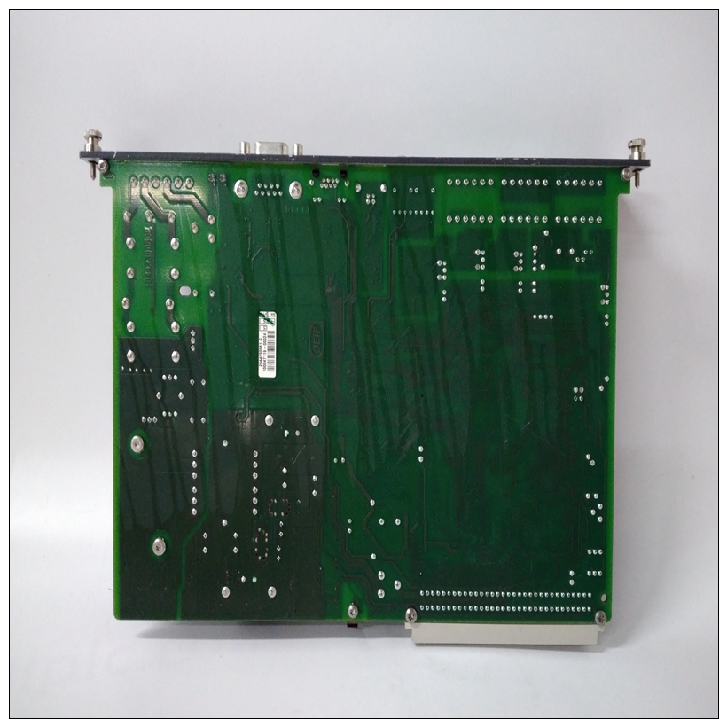
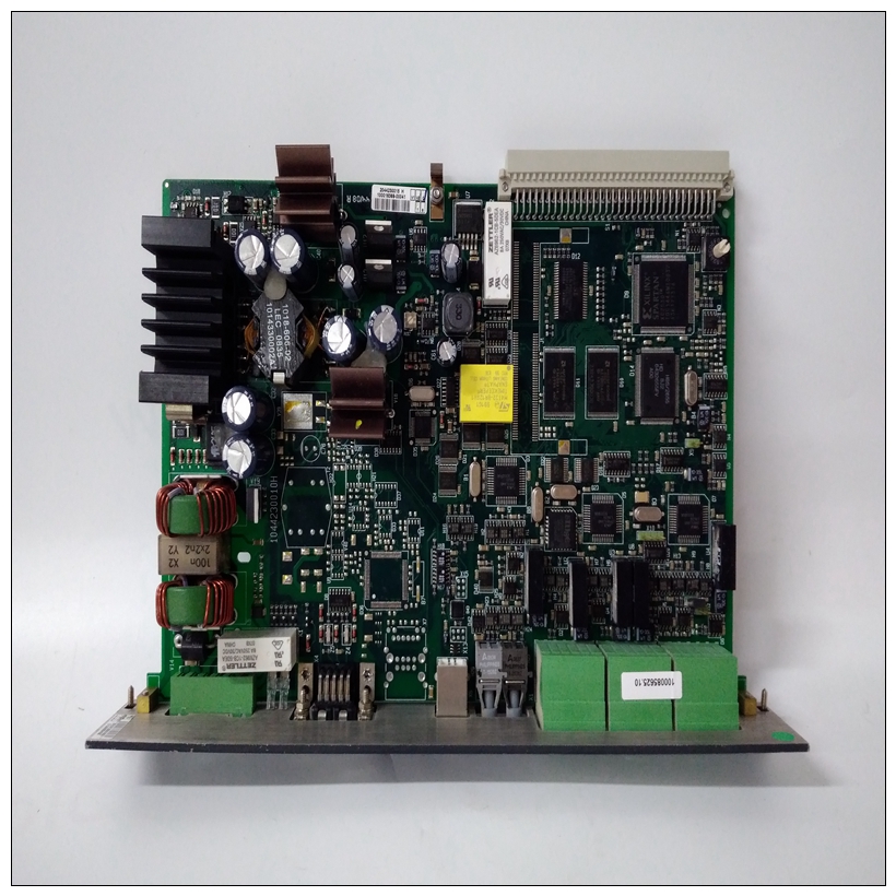
DEIF PCM4.4船舶行业卡件,PCM4.4产品重量
如果在嵌入MVME172LX VME时遇到困难控制器,请尝试以下页面上的简单故障排除步骤在呼叫帮助或将电路板送回维修之前。一些程序将板返回到工厂调试器环境。(The电路板出厂前在这些条件下进行了测试。)自检可能不会在所有用户自定义的环境中运行。支持的网络控制器模块172Bug固件支持以下VMEbus网络控制器模块。


DEIF PCM4.4船舶行业卡件显示了每个模块类型和位置的默认地址指示控制器必须驻留在何处才能由172Bug支持。通过列出的指定CLUN和DLUN访问控制器在这里CLUN和DLUN与调试器一起使用有关更多信息,请参阅下表以了解制造商的信息数据表或用户手册。作为进一步的帮助,列出还提供了文件。请注意,在许多情况下信息是初步的,文件的修订级别是如有变更,恕不另行通知有关更多信息,请参阅下表以了解制造商的信息数据表或用户手册。作为进一步的帮助,列出了还提供了文件。请注意,在许多情况下信息是初步的,文件的修订级别是如有更改,恕不另行通知。注:VME规范的早期版本如下:多功能背板总线:VMEbus1。断开系统的所有电源。2.检查是否安装了正确的调试器设备。3.从J21针脚9-10上拆下跨接线。这允许使用EPROM代替闪存。4、重新接通电源。5、“双键复位”重启系统:按下复位键同时中止开关;先释放重置,等待7秒,然后释放ABORT。6.如果出现调试提示,则转至步骤四或步骤五,如图所示表明。如果没有出现调试提示,请转至步骤六。
Solving Startup Problems
In the event of difficulty with your MVME172LX VME embedded
controller, try the simple troubleshooting steps on the following pages
before calling for help or sending the board back for repair. Some of the
procedures will return the board to the factory debugger environment. (The
board was tested under these conditions before it left the factory.) The selftests may not run in all user-customized environments.Network Controller Modules Supported
The 172Bug firmware supports following VMEbus network controller
modules. The default address for each module type and position is shown
to indicate where the controller must reside to be supported by the 172Bug.
The controllers are accessed via the specified CLUN and DLUNs listed
here. The CLUN and DLUNs are used in conjunction with the debugger
For additional information, refer to the following table for manufacturers’
data sheets or user’s manuals. As a further help, sources for the listed
documents are also provided. Please note that in many cases, the
information is preliminary and the revision levels of the documents are
subject to change without noticeRelated Specifications
For additional information, refer to the following table for manufacturers’
data sheets or user’s manuals. As a further help, sources for the listed
documents are also provided. Please note that in many cases, the
information is preliminary and the revision levels of the documents are
subject to change without notice.NOTE: An earlier version of the VME specification is available as:
Versatile Backplane Bus: VMEbus1. Disconnect all power from your system.
2. Check that the proper debugger device is installed.
3. Remove the jumper from J21, pins 9-10. This enables use of the
EPROM instead of the Flash memory.
4. Reconnect power.
5. Restart the system by “double-button reset”: press the RESET
and ABORT switches at the same time; release RESET first, wait
seven seconds, then release ABORT.
6. If the debug prompt appears, go to step IV or step V, as
indicated. If the debug prompt does not appear, go to step VI.


