


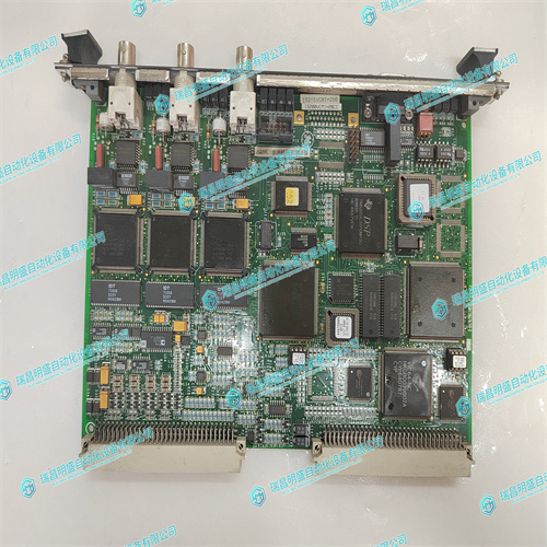
GE IS215VCMIH2BB IS200VCMIH2BCC操控器卡
GE IS215VCMIH2BB IS200VCMIH2BCC通过以下任一方法输入TCP相对于世界坐标系(表示刀具安装点)的位置:从现有目标或框架读取值单击“目标/框架值”框,然后在图形窗口或“路径和目标”浏览器中选择框架。手动输入位置和方向。在“位置”和“方向”框中,键入值。注:如果选择了“使用虚拟零件”,则位置值不能为0,0,0。至少有一个坐标必须大于0才能创建圆锥体。单击向右箭头按钮将值传输到TCP:框。如果工具应具有多个TCP,则对每个TCP重复步骤5至7。8.单击“完成”。该工具将被创建并显示在“对象”浏览器和图形窗口中。为现有几何图形创建工具数据要为现有几何图元创建工具数据,请执行以下步骤:1。确保选择了要在其中创建刀具数据的机器人。2.单击创建工具,然后从列表中选择使用现GE IS215VCMIH2BB IS200VCMIH2BCC有工具和导入的工具。3.在创建工具向导的框中输入请求的数据。4.通过将工具拖到机器人上来连接工具。
GE IS215VCMIH2BB IS200VCMIH2BCC操控器卡
Enter the position of the TCP relative to the world coordinate system, which represents the tool mounting point, by any of the methods below:Read values from existing target or frame Click in the Values from Target/Frame box, then select the frame either in the graphics window or the Paths&Targets browser. Enter position and orientation manually. In the Position and Orientation boxes, type the values. NOTE: If Use Dummy Part is selected, the position value can not be 0,0,0. At least one coordinate has to be > 0 in order for a cone to be created.Click the arrow right button to transfer the values to the TCP(s): box. If the tool shall have several TCPs, repeat steps 5 to 7 for each TCP. 8. Click Done. The tool will be created and appear in the Objects browser and in the graphics window.Creating tooldata for an existing geometry To create tooldata for an existing geometry, follow these steps: 1. Make sure the robot in which to create the tooldata is selected. 2. Click Create Tool and select Use Existing and the imported tool from the list. 3. Enter the requested data in the boxes in the Create Tool Wizard. 4. Attach the tool by dragging it to the robot.
")
公司主营优势
")
应用行业
")

