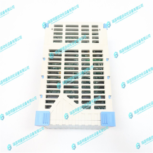
EMERSON 1C31232G03数字输入模块
电源监控逻辑提供在板上,用于监控来自LTC3288和LTC3146调节器的PGOOD信号,以确定电源输出是否在容差范围内。如果任何电源发生故障,此逻辑将关闭电源以避免任何组件损坏。如果+5.0V电源在故障状态下仍然正常,则平面红色LED(PWR fail D9)将点亮,以指示电源故障状态。4.12.3电源滤波和熔断MVME7100上的每个开关电源输入都将具有电感器,以减少反馈到+5.0V输入的开关噪声。LTC3828电源将各有一个10A保险丝,以在部件故障时保护电源不受过电流影响。4.13时钟分配时钟功能生成并分配系统运行所需的所有时钟。PCI-E时钟使用八输出差分时钟驱动器生成。PCI/PCI-X总线时钟由桥接芯片从PCI-E时钟生成。使用单个振荡器在设备附近生成单个设备所需的附加时钟。有关时钟分配,请参阅MVME7100单板计算机编程器参考手册。
Power Supply Monitor Logic is provided on-board to monitor the PGOOD signal from the LTC3828 and LTC3416 regulators to determine if the power supply outputs are within tolerance. If any of the power supplies fail, this logic shuts off the power supplies to avoid any component damage. If the +5.0V power supply is still good during a fail condition, a planar red LED (PWR FAIL D9) is illuminated to indicate the power supply fail condition. 4.12.3 Power Supply Filtering and Fusing Each of the switching power supply inputs on the MVME7100 will have an inductor to reduce switching noise from being fed back onto the +5.0V input. The LTC3828 supplies will each have a 10A fuse to protect the supplies from over-current in case of component failure. 4.13 Clock Distribution The clock function generates and distributes all of the clocks required for system operation. The PCI-E clocks are generated using an eight output differential clock driver. The PCI/PCI-X bus clocks are generated by the bridge chips from the PCI-E clock. Additional clocks required by individual devices are generated near the devices using individual oscillators. For clock assignments, refer to the MVME7100 Single Board Computer Programmer’s Reference manual.


