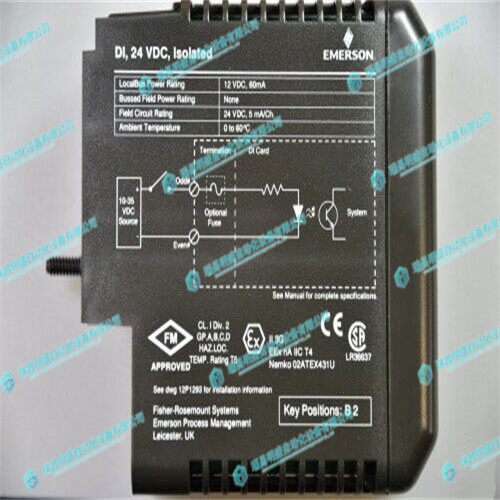
EMERSON VE4001S2T1B1控制器
区块A位于最高的1MB区块,而区块B是次高的1MB块。闪存引导块开关用于在引导块A和引导块B之间进行选择。当开关关闭时,闪存映射正常,如图3所示选择块A。当开关打开时,块B被映射到最高地址,如图4所示。闪存控制/状态寄存器中的MAP_SELECT位可以禁用跳线,并在选择块A的情况下将内存映射恢复到正常配置。4.8.1闪存MVME7100设计用于提供128MB的焊接NOR闪存。两个AMD+3.3V设备被配置为以16位模式操作,以形成32位闪存库。该闪存库也是引导库,并连接到LBC芯片选择0和1。
Block A is located at the highest 1MB block and block B is the next highest 1MB block. A flash boot block switch is used to select between boot block A and boot block B. When the switch is OFF, the flash memory map is normal and block A is selected as shown in Figure 3. When the switch is ON, block B is mapped to the highest address as shown in Figure 4. The MAP_SELECT bit in the flash Control/Status register can disable the jumper and restore the memory map to the normal configuration with block A selected. 4.8.1 Flash Memory The MVME7100 is designed to provide 128MB of soldered-on NOR flash memory. Two AMD +3.3V devices are configured to operate in 16-bit mode to form a 32-bit flash bank. This flash bank is also the boot bank and is connected to LBC Chip Select 0 and 1.


