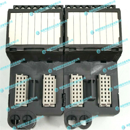
EMERSON KJ3241X1-EA1冗余串行接口接线端子
I2C接口路由至P2连接器,以访问位于转换模块上的串行EEPROM。用户可使用配置开关选择转换模块串行EEPROM的设备地址。有关开关的信息,请参阅第5章,转换模块。有关编程信息,请参阅MVME7100单板计算机程序员参考。系统内存MC864xD包括两个内存控制器。MVME7100在每个控制器上支持一组存储器。MVME7100支持512MB、1GB和2GB DDR2 SDRAMS。这提供了1GB、2GB和4GB的内存配置。MVME7100支持高达DDR533的内存速度。4.6 MVME7100的定时器计时功能由集成在MC864xD中的四个全局高分辨率定时器以及四个额外的独立32位定时器提供。四个集成32位计时器由RTC输入计时,RTC输入由1MHz时钟驱动。有关更多详细信息和/或编程信息,请参阅第117页附录B“相关文件和制造商文件”中列出的MC864xD参考手册
The I2C interface is routed to the P2 connector for access to the serial EEPROM located on the transition module. The device address for the transition module serial EEPROM is user selectable using the configuration switches. Refer to Chapter 5, Transition Module for information on the switches. For programming information, see the MVME7100 Single Board Computer Programmer’s Reference.System Memory The MC864xD includes two memory controllers. The MVME7100 supports one bank of memory on each controller. The MVME7100 supports 512MB, 1GB and 2GB DDR2 SDRAMS. This provides memory configurations of 1GB, 2GB, and 4GB. The MVME7100 supports memory speeds up to DDR533. 4.6 Timers Timing functions for the MVME7100 are provided by four global high-resolution timers integrated into the MC864xD plus four additional independent 32-bit timers. The four integrated 32-bit timers are clocked by the RTC input which is driven by a 1MHz clock. Refer to the MC864xD reference manual, listed in Appendix B, Related Documentation and Manufacturers’ Documents on page 117 for additional details and/or programming information


