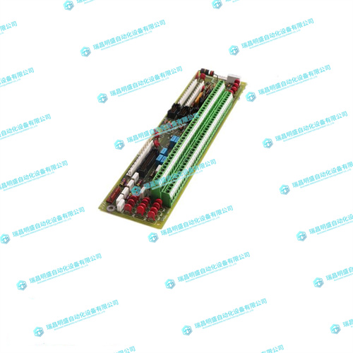
GE DS200PTBAG1ADC工控控制卡件
同时向内移动喷油器/推料器操纵杆。8.验证转换模块是否正确就位,并使用位于喷油器/喷射器杆附近的两个螺钉将其固定到底盘上。9.将适当的电缆连接到转换模块。要从机箱上卸下转换模块,请颠倒程序并按下红色锁定卡舌(仅限IEEE手柄)以拔出电路板。PMC PMC连接器的位置可支持两个单宽PMC或一个双宽PMC。PMC站点1通过Jn4连接器支持前PMC I/O和后PMC I/O。PMC 1 I/O路由至VME P2接头。PMC站点2仅支持前端PMC I/O,没有Jn4连接器。PMC 1 Jn4用户I/O信号仅支持低电流高速信号,因此不支持电流轴承电源的使用。在大多数情况下,PMC已经安装在底板上。用户配置的交换机可通过安装的PMC访问。板载PMC站点配置为支持+3.3V I/O PMC模块。车载PMC站点不支持+5.0V I/O PMC模块。
Simultaneously move the injector/ejector levers in an inward direction. 8. Verify that the transition module is properly seated and secure it to the chassis using the two screws located adjacent to the injector/ejector levers. 9. Connect the appropriate cables to the transition module. To remove the transition module from the chassis, reverse the procedure and press the red locking tabs (IEEE handles only) to extract the board.PMC The PMC connectors are placed to support two single-width PMCs or one double-width PMC. PMC site 1 supports front PMC I/O and rear PMC I/O via the Jn4 connector. PMC 1 I/O is routed to the VME P2 connector. PMC site 2 only supports front PMC I/O and does not have a Jn4 connector. The PMC 1 Jn4 user I/O signals only support low-current highspeed signals and thus do not support current-bearing power supply usage. In most cases, the PMCs are already in place on the baseboard. The user-configured switches are accessible with the PMCs installed. The onboard PMC sites are configured to support +3.3V I/O PMC modules. The onboard PMC sites do not support +5.0V I/O PMC modules.


