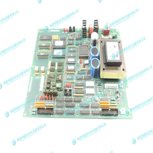
GE DS200UPLAG1BDA电路板
PULSE INPUT 3:请参阅上述PULSE Input1描述,并将PULSE INPUT 1的所有引用替换为PULSE INPUT 3。PULSE INPUT 4:请参阅上述PULSE Input1描述,并将PULSE INPUT 1的所有引用替换为PULSE INPUT 4。脉冲输入1+2+3+4:此处显示总脉冲输入值。总计的脉冲输入基于S2系统设置\脉冲输入\脉冲输入总计设置点。上次重置时间:此消息显示上次清除脉冲输入值的时间和日期。S1 PQM SETUP\CLEAR DATA\CLEAR PULSE INPUT VALUES(S1 PQM设置\清除数据\清除脉冲输入值)设定值清除脉冲输入数值。模拟输入:此消息显示按用户定义的名称和单位缩放的测量的4至20 mA模拟输入。模拟输入可以通过开关输入和输出继电器进行配置,以多路复用两个模拟输入信号。
PULSE INPUT 3: See the PULSE INPUT 1 description above and replace all references to PULSE INPUT 1 with PULSE INPUT 3. PULSE INPUT 4: See the PULSE INPUT 1 description above and replace all references to PULSE INPUT 1 with PULSE INPUT 4. PULSE IN 1+2+3+4: The totalized pulse input value is displayed here. The pulse inputs totalized is based on the S2 SYSTEM SETUP \ PULSE INPUT \ PULSE INPUT TOTAL setpoint.TIME OF LAST RESET: This message displays the time and date when the pulse input values were last cleared. The S1 PQM SETUP \ CLEAR DATA \ CLEAR PULSE INPUT VALUES setpoint clears the pulse input values.ANALOG INPUT: This message displays the measured 4 to 20 mA analog input scaled to the user defined name and units. The analog input can be configured via a switch input and output relay to multiplex two analog input signals.


