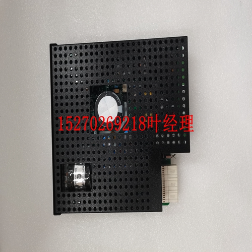
GE燃机 IS200VPWRH1A系统模块卡件
驱动器/接收器端口2 EIA-485/EIA-422 2-36计算机组文献中心网站硬件准备2 3-1 3 3调试这与同时按下重置和中止开关相同。如果用户设置损坏或不符合健全性检查,则可以使用此功能。有关Flash/PROM默认值,请参阅ENV命令(第5章)。位#2(GPI2)11-12保留供将来使用。位#3(GPI3)9-10设置为0(低)时,通知调试器它正在闪存中执行。当设置为1(高)时,如在没有VMEbus模型中设置的那样,通知调试器它正在PROM之外执行。Bit#4(GPI4)7-8对应用程序开放。Bit#5(GPI5)5-6对应用程序开放。Bit#6(GPI6)3-4对应用程序开放。Bit#7(GPI7)1-2对应用程序开放。Bit J22引脚说明3-6计算机组文献中心网站调试器一般信息3 3。您可以通过安装在MVME162FX板连接器J10上的串行接口模块(SIMM)配置Z85230串行通信控制器的端口B。有五个串行接口模块可用:–EIA-232-D DTE(SIMM05)–EIA-232D DCE(SIMM 06)–EIA-530 DTE(SIM M07)–EIA-530 DCE(SIM M 08)–EIA 485或EIA-422 DTE或DCE(均带有SIMM09)有关卸下和/或安装SIMM的信息,请参阅第2章。4.报头J11和J12上的跳线配置串行端口1和2以驱动或接收由TXC和RXC信号线提供的时钟信号。工厂为异步通信配置模块,即不安装跳线。如果应用程序需要为同步通信配置端口1和2,请参阅第2章。5.如果使用162Bug的PROM版本(例如,在没有VMEbus、空白Flash版本的MVME162FX中),请将PROM设备安装在插座U47中。确保物理芯片方向正确,即PROM的平角与MVME162FX控制器上PROM插槽的相应部分对齐。检查收割台J21上的跳线安装尺寸是否正确。连接J21上27C080设备的针脚1和2,或27C040设备的针脚2和3。出厂默认值为2和3。拆下J22针脚9和10上的跨接导线。3除雾器一般信息安装和启动http://www.mcg.mot.com/literature3-73注意:如果您希望在后续会话中使用闪存而不是PROM执行调试器,则需要在通电后初始化闪存,如步骤12所述。6.标头J24上的跳线将IP总线时钟配置为8MHz(在MVME162-4xx和-5xx板上)或32MHz(仅限MVME162-5xx板)。工厂配置在J24引脚1和2之间安装一条跳线,用于8MHz时钟。验证此设置是否适合您的应用程序。7.标头J25上的跳线启用/禁用MVME162FX上的IP总线选通功能。工厂配置在J25引脚1和2之间放置跳线,以将Strobe*信号连接到IP2芯片。验证选通线路是否连接在
DRIVER/RECEIVER PORT 2 EIA-485/EIA-422 2-36 Computer Group Literature Center Web Site Hardware Preparation 2 3-1 3 3Debugger This is the same as depressing the RESET and ABORT switches at the same time. This feature can be used in the event the user setup is corrupted or does not meet a sanity check. Refer to the ENV command (Chapter 5) for the Flash/PROM defaults. Bit #2 (GPI2) 11-12 Reserved for future use. Bit #3 (GPI3) 9-10 When set to 0 (low), informs the debugger that it is executing out of the Flash memory. When set to 1 (high), as set in no-VMEbus models, informs the debugger that it is executing out of the PROM. Bit #4 (GPI4) 7-8 Open to your application. Bit #5 (GPI5) 5-6 Open to your application. Bit #6 (GPI6) 3-4 Open to your application. Bit #7 (GPI7) 1-2 Open to your application. Bit J22 Pins Description 3-6 Computer Group Literature Center Web Site Debugger General Information 3 3. You may configure Port B of the Z85230 serial com- munications controller via a serial interface module (SIMM) which is installed at connector J10 on the MVME162FX board. Five serial interface modules are available: – EIA-232-D DTE (SIMM05) – EIA-232-D DCE (SIMM06) – EIA-530 DTE (SIMM07) – EIA-530 DCE (SIMM08) – EIA-485, or EIA-422 DTE or DCE (all with SIMM09) Refer to Chapter 2 for information on removing and/or installing a SIMM. 4. Jumpers on headers J11 and J12 configure serial ports 1 and 2 to drive or receive clock signals provided by the TXC and RXC signal lines. The factory configures the module for asynchronous communication, that is, installs no jumpers. Refer to Chapter 2 if your application requires configuring ports 1 and 2 for synchronous communication. 5. If using a PROM version of the 162Bug (e.g., in no-VMEbus, blank-Flash versions of the MVME162FX), install the PROM device in socket U47. Be sure that the physical chip orientation is correct — that is, with the flattened corner of the PROM aligned with the corresponding portion of the PROM socket on the MVME162FX controller. Check the jumper installation on header J21 for correct size. Connect pins 1 and 2 on J21 for 27C080 devices, or pins 2 and 3 for 27C040 devices. The factory default is 2 and 3. Remove the jumper on J22 pins 9 and 10. 3Debugger General Information Installation and Startup http://www.mcg.mot.com/literature 3-7 3 Note If you wish to execute the debugger out of flash memory rather than from PROM in subsequent sessions, it will be necessary to initialize the flash memory after power-up as described in Step 12. 6. The jumper on header J24 configures the IP bus clock for either 8MHz (on both MVME162-4xx and -5xx boards) or 32MHz (on MVME162-5xx boards only). The factory configuration installs a jumper between J24 pins 1 and 2 for an 8MHz clock. Verify that this setting is appropriate for your application. 7. The jumper on header J25 enables/disables the IP bus strobe function on the MVME162FX. The factory configuration puts a jumper between J25 pins 1 and 2 to connect the Strobe∗ signal to the IP2 chip. Verify that the strobe line should be connected in your


