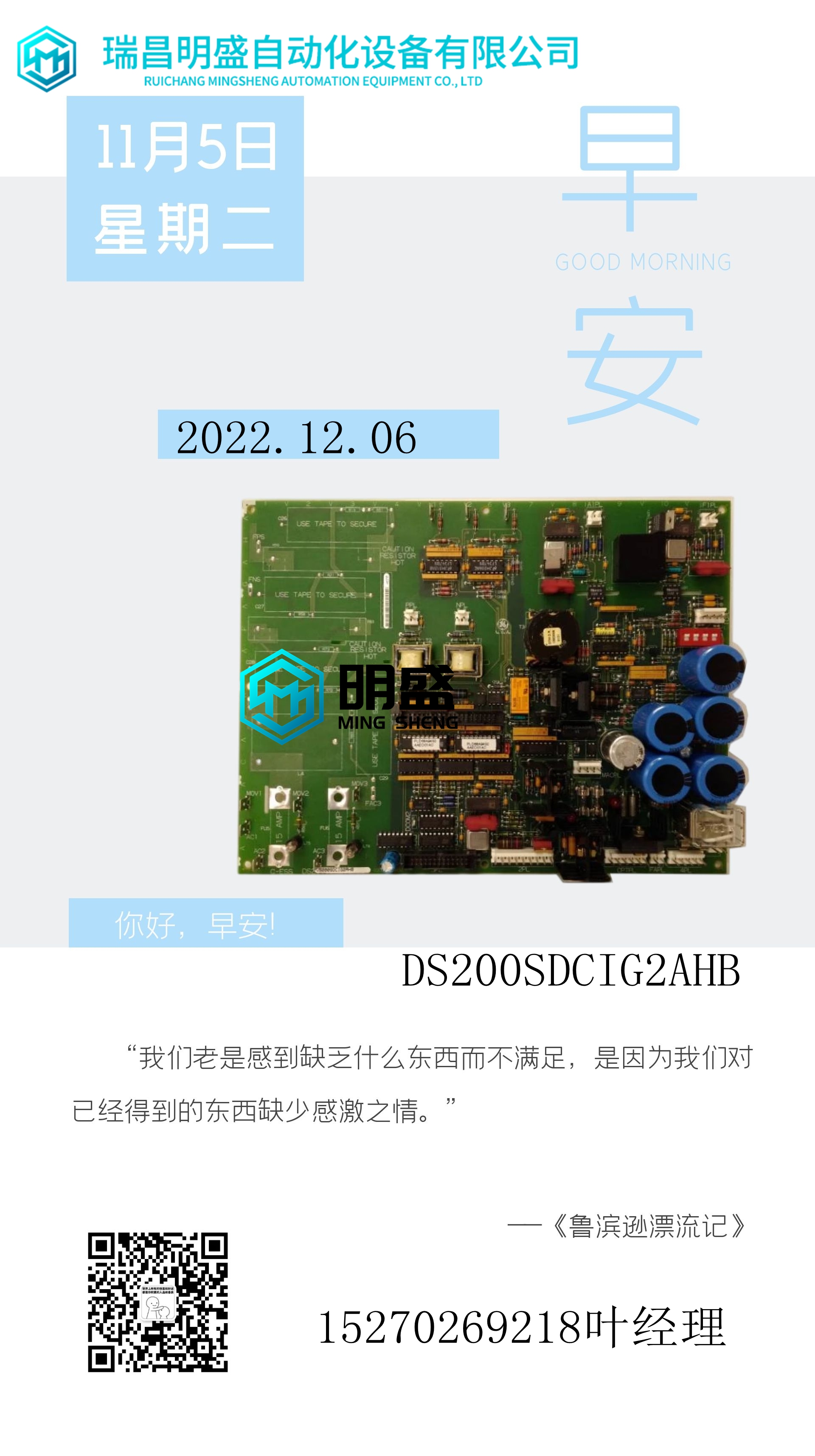
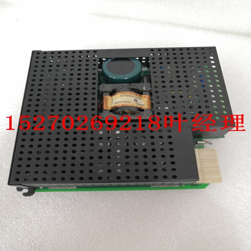
GE燃机卡 DS200ITXDG1A工控模块卡件
通电时拆除模块!警告:本设备中存在可能导致死亡的危险电压。在处理、测试和调整时要格外小心。2.按照用户手册中的说明卸下机箱盖。3.从要安装控制器的卡插槽中卸下填充面板。–如果您打算将MVME162FX用作系统控制器,它必须占用最左侧的卡插槽(插槽1)。系统控制器必须位于插槽1中,以正确启动总线授权菊花链,并确保IACK菊花链驱动程序正常运行。–如果您不打算将MVME162FX用作系统控制器,它可能会占用任何未使用的双倍高度卡插槽。4.将控制器滑入所选卡槽。确保模块正确安装在背板上的P1和P2连接器中。不要损坏或弯曲接头针脚。5.使用提供的螺钉将控制器固定在机箱中,与横向安装导轨保持良好接触,以尽量减少射频发射。6.将MVME712系列转换模块安装在VME机箱的前部或后部。请注意,要安装MVME712M(安装说明http://www.mcg.mot.com/literature2-19 2具有双宽前面板),您可能需要移动机箱中的其他模块。注意:如果您打算在EIA-530配置或EIA-485/EIA422配置中使用带有端口B的MVME162FX嵌入式控制器,请不要安装P2或LCP2适配器板和MVME712系列转换模块。它们与EIA-530接口和EIA485/EIA-422接口不兼容。有关更多信息,请参阅第1章“功能说明”中的MVME162FX串行端口2。注:某些VME背板(如摩托罗拉“模块化机箱”系统中使用的背板)具有自动跳转功能,用于自动传播IACK和BG信号。步骤7不适用于这种背板设计。7.在机箱背板上,从控制器占用的卡插槽的标头中卸下中断确认(IACK)和总线授权(BG)跳线。8.将P2适配器板或LCP2适配器板和电缆连接到控制器的背板连接器P2。这为EIA-232-D串行端口、SCSI端口和LAN以太网端口处的终端或其他外围设备提供了连接点。有关安装P2或LCP2适配器板和MVME712系列转换模块的信息,请参阅附录F中相关文档中列出的手册。请注意,《MVME162FX嵌入式控制器程序员参考指南》提供了一些连接图。9.将适当的电缆连接到串行端口、SCSI端口和LAN以太网端口的面板连接器。2-20计算机组文献中心网站硬件准备2–请注意,某些电缆未随MVME712系列模块提供,必须由用户制造或购买。摩托罗拉建议所有外围连接使用屏蔽电缆,以尽量减少辐射。10.将外围设备连接到电缆。附录A提供了支持的EIA-232-D、EIA-530和EIA485/EIA-422信号的详细信息。附录B描述了SCSI(小型计算机系统接口)I/O总线连接。附录C描述了以太网LAN(局域网)端口连接。11.在系统中安装任何其他所需的VMEmodule。12.装回机箱盖。13.将电源电缆连接到交流电源,并打开设备电源。系统注意事项MVME162FX嵌入式控制器从VMEbus背板连接器P1和P2获取电源。P2还用于32位传输中的高16位数据,以及扩展寻址模式中使用的高8位地址线。如果主板未连接到VMEbus背板连接器P1和P2,控制器可能无法正常工作。无论控制器作为VMEbus主控制器还是VMEbus从控制器,它都配置了32位地址和32位数据(A32/D32)。然而,它在第1章所示的地址范围内处理A16或A24设备。系统中的D8和/或D16设备必须由MC68040/MC68LC040软件处理。请参阅MVME162FX中的内存映射
remove modules while power is applied. ! Warning Dangerous voltages, capable of causing death, are present in this equipment. Use extreme caution when handling, testing, and adjusting. 2. Remove the chassis cover as instructed in its user’s manual. 3. Remove the filler panel from the card slot where you are going to install the controller. – If you intend to use the MVME162FX as system controller, it must occupy the leftmost card slot (slot 1). The system controller must be in slot 1 to correctly initiate the bus-grant daisy-chain and to ensure proper operation of the IACK daisy-chain driver. – If you do not intend to use the MVME162FX as system controller, it can occupy any unused double-height card slot. 4. Slide the controller into the selected card slot. Be sure the module is seated properly in the P1 and P2 connectors on the backplane. Do not damage or bend the connector pins. 5. Secure the controller in the chassis with the screws provided, making good contact with the transverse mounting rails to minimize RF emissions. 6. Install the MVME712 series transition module in the front or the rear of the VME chassis. Note that to install an MVME712M (which Installation Instructions http://www.mcg.mot.com/literature 2-19 2 has a double-wide front panel) you may need to shift other modules in the chassis. Note If you intend to use the MVME162FX Embedded Controller with Port B in an EIA-530 configuration or an EIA-485/EIA422 configuration, do not install the P2 or LCP2 Adapter Board and the MVME712 series transition module. They are incompatible with the EIA-530 interface and the EIA485/EIA-422 interface. Refer to MVME162FX Serial Port 2 in Chapter 1, Functional Description for additional information. Note Some VME backplanes (e.g., those used in Motorola ‘‘Modular Chassis’’ systems) have an autojumpering feature for automatic propagation of the IACK and BG signals. Step 7 does not apply to such backplane designs. 7. On the chassis backplane, remove the INTERRUPT ACKNOWLEDGE (IACK) and BUS GRANT (BG) jumpers from the header for the card slot occupied by the controller. 8. Connect the P2 Adapter Board or LCP2 Adapter Board and cable(s) to controller’s backplane connector P2. This provides a connection point for terminals or other peripherals at the EIA-232-D serial ports, SCSI ports, and LAN Ethernet port. For information on installing the P2 or LCP2 Adapter Board and the MVME712 series transition module(s), refer to the manuals listed in Related Documentation in Appendix F. Note that the MVME162FX Embedded Controller Programmer’s Reference Guide provides some connection diagrams. 9. Connect the appropriate cable(s) to the panel connectors for the serial ports, SCSI port, and LAN Ethernet port. 2-20 Computer Group Literature Center Web Site Hardware Preparation 2 – Note that some cables are not provided with the MVME712 series module and must be made or purchased by the user. Motorola recommends shielded cable for all peripheral connections to minimize radiation. 10. Connect the peripheral(s) to the cable(s). Appendix A provides detailed information on the EIA-232-D, EIA-530, and EIA485/EIA-422 signals supported. Appendix B describes the SCSI (Small Computer System Interface) I/O bus connections. Appendix C describes the Ethernet LAN (Local Area Network) port connections. 11. Install any other required VMEmodules in the system. 12. Replace the chassis cover. 13. Connect the power cable to the AC power source and turn the equipment power ON. System Considerations The MVME162FX Embedded Controller draws power from VMEbus backplane connectors P1 and P2. P2 is also used for the upper 16 bits of data in 32-bit transfers, and for the upper 8 address lines used in extended addressing mode. The controller may not function properly without its main board connected to VMEbus backplane connectors P1 and P2. Whether the controller operates as VMEbus master or VMEbus slave, it is configured for 32 bits of address and 32 bits of data (A32/D32). However, it handles A16 or A24 devices in the address ranges indicated in Chapter 1. D8 and/or D16 devices in the system must be handled by the MC68040/MC68LC040 software. Refer to the memory maps in the MVME162FX


