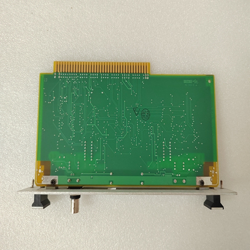
HONEYWELL 51306521-175 CC-TAON11模块控制器
启动将被阻止,直到有足够的热容量。5.4.2平均电机负载路径:实际值×A3学习数据×平均电机负载469可以学习一段时间内的平均电机负载。该时间由S1 469 SETUP(设置)×PREFERENCES(首选)×AVERAGE MOTOR LOAD CALC.PERIOD(平均电机负载计算周期)设定值指定(默认为15分钟)。该计算是一个滑动窗口,在电机启动期间被忽略。n电机启动n[输入]了解更多学习加速时间:0.0 s范围:0.0至200.0秒。学习启动电流:0 A范围:0至50000 A学习启动容量:0%使用范围:0到100%上次加速时间:0.0s范围:0.0~200.0秒。最后启动电流:0 A范围:0至50000 A最后启动容量:0%使用范围:0到100%平均电机负载n[ENTER]了解更多平均电机负载学习值:0.00 x FLA范围:0.00到20.00 ENTER ESCAPE(输入退出)RTD最大值路径:实际值×A3学习数据×RTD最大值469将学习每个RTD的最大温度。可使用S1 469 SETUP(设置)×CLEAR DATA(清除数据)×CLER RTD MAXIMUMS(清除RTD最大值)设定点清除此信息。如果在S8 RTD TEMPERATURE(S8 RTD温度)中未编程RTD,则尝试输入这组信息时将显示以下闪烁信息。n RTD MAXIMUMS n[ENTER]更多RTD#1最大温度:40°C范围:-50至250°C,无RTD(开路),----(短路)。仅当模拟输入自上次清除以来至少有1个最大值时才可见。该信息可通过S1 469 SETUP?CLEAR DATA?CLEAR ANALOG I/P MIN/MAX设置点清除。清除数据后,每个模拟输入的当前值将作为最小值和最大值的起点加载。输入名称和单位将反映为每个输入编程的名称。如果在S12模拟输入/输出中未编程模拟输入,当试图输入这组信息时,将出现以下闪烁信息。n ANALOG IN MIN/MAX n[ENTER](模拟输入最小值/最大值),了解更多模拟I/P 1最小值:O单位范围:–50000至50000。如果模拟输入设置为无,则不可见。将模拟输入名称反映为编程的模拟I/P 1 MAX:0单位范围:-50至250°C,无RTD(开路),----(短路)。如果RTD设置为无,则不可见;将RTD名称反映为编程的模拟I/P 2 MIN:O单位范围:-50至250°C,无RTD(开路),----(短路)。如果RTD设置为无,则不可见;将RTD名称反映为编程的模拟I/P 2最大值:0û♥MESSAGE ESCAPE MESSAGE ESCAPE MESSAGE ESCAPE MISSAGE ESCAP MESSAGE ESCAPE MESAGE ESCAPE GE Multilin 469电机管理继电器5-19 5实际值5.5 A4维护5 5.5A4维护5.5.1跳闸计数器路径:实际值×A4维护跳闸计数器n跳闸计数器n[ENTER]了解更多跳闸总数:0范围:0至50000不完整序列跳闸:0范围:0到50000由降压启动功能输入开关跳闸引起:0范围0到50000由于远程、速度、减载、压力、振动或通用开关跳闸功能转速表跳闸:0量程0到50000。由编程为转速计过载跳闸的数字输入引起:0范围:0至50000短路跳闸:0范围0至50000机械堵塞跳闸:0量程0至50000欠电流跳闸:0幅度0至50000电流不平衡跳闸:达到50000,所有计数器复位。可使用S1 469 SETUP(设置)×CLEAR DATA(清除数据)×CLER TRIP COUNTERS(清除跳闸计数器)设定点清除该信息。5.5.2通用计数器路径:实际值×A4维护×通用计数器469个通用计数器中的两个计数电机启动次数或启动尝试次数,以及一段时间内为启动给定电机而执行的紧急重启次数。在排除电机故障时,这可能是有用的信息。当这些计数器中的任何一个达到50000时,该计数器将重置为0。该信息可通过S1 469 SETUP(设置)×INSTALLATION(安装)×RESET MOTOR information(重置电机信息)设定点清除。469个常规计数器中的另一个计数器将统计一段时间内执行的启动器操作数。每当电机停止时,无论是跳闸还是正常停止,该计数器都会递增
Starting will be blocked until there is sufficient thermal capacity. 5.4.2 AVERAGE MOTOR LOAD PATH: ACTUAL VALUES Õ× A3 LEARNED DATA Õ× AVERAGE MOTOR LOAD The 469 can learn the average motor load over a period of time. This time is specified by the S1 469 SETUP Õ× PREFERENCES Õ× AVERAGE MOTOR LOAD CALC. PERIOD setpoint (default 15 minutes). The calculation is a sliding window and is ignored during motor starting. n MOTOR STARTING n [ENTER] for more LEARNED ACCELERATION TIME: 0.0 s Range: 0.0 to 200.0 sec. LEARNED STARTING CURRENT: 0 A Range: 0 to 50000 A LEARNED STARTING CAPACITY: 0% used Range: 0 to 100% LAST ACCELERATION TIME: 0.0 s Range: 0.0 to 200.0 sec. LAST STARTING CURRENT: 0 A Range: 0 to 50000 A LAST STARTING CAPACITY: 0% used Range: 0 to 100% n AVERAGE MOTOR LOAD n [ENTER] for more AVERAGE MOTOR LOAD LEARNED: 0.00 x FLA Range: 0.00 to 20.00 ENTER ESCAPE ð ð MESSAGE ESCAPE MESSAGE ESCAPE MESSAGE ESCAPE MESSAGE ESCAPE MESSAGE ESCAPE ENTER ESCAPE ð ð GE Multilin 469 Motor Management Relay 5-17 5 ACTUAL VALUES 5.4 A3 LEARNED DATA 5 5.4.3 RTD MAXIMUMS PATH: ACTUAL VALUES Õ× A3 LEARNED DATA Õ× RTD MAXIMUMS The 469 will learn the maximum temperature for each RTD. This information can be cleared using the S1 469 SETUP Õ× CLEAR DATA Õ× CLEAR RTD MAXIMUMS setpoint. If no RTDs are programmed in S8 RTD TEMPERATURE, the following flash message will appear when an attempt is made to enter this group of messages. n RTD MAXIMUMS n [ENTER] for more RTD #1 MAX. TEMP.: 40°C Range: –50 to 250°C, No RTD (open), ---- (shorted). Seen only if at least 1 maximum values of the analog inputs since they were last cleared. This information can be cleared with the S1 469 SETUP Õ× CLEAR DATA Õ× CLEAR ANALOG I/P MIN/MAX setpoint. When the data is cleared, the present value of each analog input will be loaded as a starting point for both minimum and maximum. The name of the input and the units will reflect those programmed for each input. If no Analog Inputs are programmed in S12 ANALOG I/O, the following flash message will appear when an attempt is made to enter this group of messages. n ANALOG IN MIN/MAX n [ENTER] for more ANALOG I/P 1 MIN: O Units Range: –50000 to 50000. Not seen if Analog Input is set as None. Reflects the Analog Input Name as programmed ANALOG I/P 1 MAX: 0 Units Range: –50 to 250°C, No RTD (open), ---- (shorted). Not seen if RTD set to None; reflects RTD Name as programmed ANALOG I/P 2 MIN: O Units Range: –50 to 250°C, No RTD (open), ---- (shorted). Not seen if RTD set to None; reflects RTD Name as programmed ANALOG I/P 2 MAX: 0 ð ð MESSAGE ESCAPE MESSAGE ESCAPE MESSAGE ESCAPE MESSAGE ESCAPE MESSAGE ESCAPE MESSAGE ESCAPE MESSAGE ESCAPE GE Multilin 469 Motor Management Relay 5-19 5 ACTUAL VALUES 5.5 A4 MAINTENANCE 5 5.5A4 MAINTENANCE 5.5.1 TRIP COUNTERS PATH: ACTUAL VALUES Õ× A4 MAINTENANCE Õ TRIP COUNTERS n TRIP COUNTERS n [ENTER] for more TOTAL NUMBER OF TRIPS: 0 Range: 0 to 50000 INCOMPLETE SEQUENCE TRIPS: 0 Range: 0 to 50000 Caused by the Reduced Voltage Start feature INPUT SWITCH TRIPS: 0 Range: 0 to 50000 Caused by Remote, Speed, Load Shed, Pressure, Vibration, or General Purpose Switch Trip features TACHOMETER TRIPS: 0 Range: 0 to 50000. Caused by Digital Input programmed as Tachometer OVERLOAD TRIPS: 0 Range: 0 to 50000 SHORT CIRCUIT TRIPS: 0 Range: 0 to 50000 MECHANICAL JAM TRIPS: 0 Range: 0 to 50000 UNDERCURRENT TRIPS: 0 Range: 0 to 50000 CURRENT UNBALANCE TRIPS: reaches 50000, all counters reset. This information can be cleared using the S1 469 SETUP Õ× CLEAR DATA Õ× CLEAR TRIP COUNTERS setpoint. 5.5.2 GENERAL COUNTERS PATH: ACTUAL VALUES Õ× A4 MAINTENANCE Õ× GENERAL COUNTERS Two of the 469 general counters count the number of motor starts or start attempts and the number of Emergency Restarts performed to start a given motor over time. This may be useful information when troubleshooting a motor failure. When either of these counters reaches 50000, that counter will reset to 0. This information can be cleared with the S1 469 SETUP Õ× INSTALLATION Õ× RESET MOTOR INFORMATION setpoint. Another of the 469 General counters will count the number of starter operations performed over time. This counter is incremented any time the motor is stopped, either by a trip or normal stop


