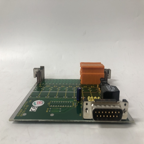
HONEYWELL 51306733-175 CC-TAID01模块备件,工控模块
编程模拟输入名称1-2 0单位范围:–100000至100000仅当模拟输入差异1-2设置为Abs Diff Reflects时可见模拟输入名称编程模拟输入名3-4 0百分比范围:–5100至4900%仅当模拟输出差异3-4设置为%Diff Refracts时可见下一页编程的模拟输入名称可用于确定VT和CT是否处于正确相位,以及其极性是否正确。不正确接线引起的问题是极高的不平衡水平(CT)或错误的功率读数(CT和VT)或相位反转跳闸(VT)。要纠正接线,只需启动电机并记录相量。使用下表以及记录的相量、系统旋转、VT连接类型和电机功率因数,可以确定正确的相量。注意,Va的相位角(如果为δ,则为Vab)始终假设为0°,并且是所有角度测量的参考。常见问题包括:相位电流与正确位置相距180°(CT极性反转)相位电流或电压120°或240°输出(CT/VT相位错误)n PHASORS n[ENTER]更多Va PHASOR 0.0%AT 0°Lag Vb PHASOR 0.0%AT 0℃Lag Vc PHASOR 0.01%AT 0℃Lag Ia PHASOR0.0%AT 1°Lag Ib PHASSOR 0.0%AT 2°Lag Ic PHASOR 0.0%AT 3°Lag ENTER ESCAPE信息逃生信息逃生GE Multilin 469电机管理继电器5-15 5实际值5.3 A2测量数据5表5–1:三相WYE VT连接ABC旋转72.5°=0.3 pf滞后45°=0.7 pf滞后0°=1.00学习数据5实际值5 5.4A3学习数据5.4.1电机启动路径:实际值×A3学习数据469学习加速时间,启动电流以及电机启动期间所需的热容量。该数据是根据最近五次启动累积的。469还保存了上次加速时间、上次启动电流和上次启动容量的统计数据。可使用S1 469 SETUP(设置)×INSTALLATION(安装)×reset MOTOR information(重置电机信息)设定点将该信息重置为默认值。如果起动过程中电机负载相对一致,则可使用学习加速度时间微调加速度保护。学习的加速时间将是最近五次成功启动中最长的时间。从电机电流从零到大于过载拾取的转变,直到线路电流降至过载拾取水平以下,测量时间。在电机电流从零过渡到大于过载拾取200 ms后,测量学习起动电流。这应确保测量的电流是对称的。显示的值是最近5次成功启动的平均值。如果少于5次启动,则整个5次启动的平均值为0。学习启动容量用于确定是否有足够的热容量允许启动(有关启动禁止的更多信息,请参阅第4–48页第4.8.2节:启动禁止)。如果没有足够的热容量进行启动,将发出启动禁止。
Input Name as programmed ANALOG 1-2 0 Units Range: –100000 to 100000 Seen only if Analog In Diff 1-2 set to Abs Diff Reflects Analog Input Name as programmed ANALOG 3-4 0 Percent Range: –5100 to 4900% Seen only if Analog In Diff 3-4 set to %Diff Reflects Analog Input Name as programmed ANALOG 3-4 0 Units Range: –100000 to 100000 Seen only if Analog In Diff 3-4 set to Abs Diff Reflects Analog Input Name as programmed the following page can be used to determine if VTs and CTs are on the correct phases and that their polarity is correct. Problems arising from incorrect wiring are extremely high unbalance levels (CTs) or erroneous power readings (CTs and VTs) or phase reversal trips (VTs). To correct wiring, simply start the motor and record the phasors. Using the tables below along with recorded phasors, system rotation, VT connection type, and motor power factor the correct phasors can be determined. Note that the phase angle for Va (Vab if delta) is always assumed to be 0° and is the reference for all angle measurements. Common problems include: Phase currents 180° from proper location (CT polarity reversed) Phase currents or voltages 120 or 240° out (CT/VT on wrong phase) n PHASORS n [ENTER] for more Va PHASOR 0.0% AT 0°Lag Vb PHASOR 0.0% AT 0°Lag Vc PHASOR 0.0% AT 0°Lag Ia PHASOR 0.0% AT 0°Lag Ib PHASOR 0.0% AT 0°Lag Ic PHASOR 0.0% AT 0°Lag ENTER ESCAPE ð ð MESSAGE ESCAPE MESSAGE ESCAPE MESSAGE ESCAPE MESSAGE ESCAPE MESSAGE ESCAPE GE Multilin 469 Motor Management Relay 5-15 5 ACTUAL VALUES 5.3 A2 METERING DATA 5 Table 5–1: THREE-PHASE WYE VT CONNECTION ABC Rotation 72.5° = 0.3 pf lag 45° = 0.7 pf lag 0° = 1.00 LEARNED DATA 5 ACTUAL VALUES 5 5.4A3 LEARNED DATA 5.4.1 MOTOR STARTING PATH: ACTUAL VALUES Õ× A3 LEARNED DATA Õ MOTOR STARTING The 469 learns the acceleration time, the starting current, as well as, the thermal capacity required during motor starts. This data is accumulated based on the last five starts. The 469 also keeps statistics for last acceleration time, last starting current, and last starting capacity. This information can be reset to default using the S1 469 SETUP Õ× INSTALLATION Õ× RESET MOTOR INFORMATION setpoint. If motor load during starting is relatively consistent, the LEARNED ACCELERATION TIME may be used to fine tune the acceleration protection. Learned acceleration time will be the longest time of the last five successful starts. The time is measured from the transition of motor current from zero to greater than overload pickup, until line current falls below the overload pickup level. LEARNED STARTING CURRENT is measured 200 ms after the transition of motor current from zero to greater than overload pickup. This should ensure that the measured current is symmetrical. The value displayed is the average of the last 5 successful starts. If there are less than 5 starts, 0s will be averaged in for the full 5 starts. The LEARNED STARTING CAPACITY is used to determine if there is enough thermal capacity to permit a start (refer to Section 4.8.2: Start Inhibit on page 4–48 for more information on start inhibit). If there is not enough thermal capacity for a start, a start inhibit will be issued.


