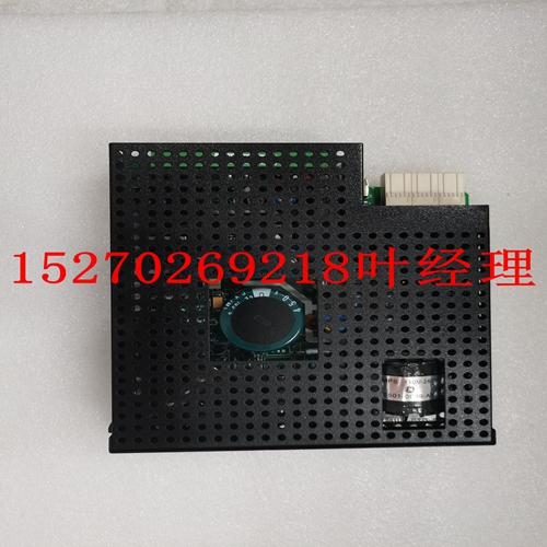
IS200AEADH1ACA工控自动化卡件
50或60赫兹。该电压导致电流在转子中流动,也以线频率流动,产生的热量(I2R)是有效转子电阻的函数。在50或60 Hz时,转子笼的电抗导致电流在转子棒的外缘流动。因此,转子的有效电阻在锁定转子状态下达到最大值,转子加热也是如此。当电机以额定速度运行时,转子中感应的电压处于低频(约1Hz),因此,转子的有效电阻显著降低。在运行过载期间,电机热极限通常由定子参数决定。某些特殊电机可能全定子或全转子受限。在加速过程中,电机滑动的动态特性决定了转子阻抗也是动态的,需要第三个过载热极限特性。下图显示了典型的热极限曲线。显示了80%电压下高惯性负载的电机启动特性。如果电机启动更快,则不需要热极限曲线的明显特征,运行过载曲线将与锁定转子安全失速时间相结合,以产生单个过载曲线。电机制造商应为其销售的任何电机提供安全失速时间或热极限曲线。为了对469进行最大程度的保护编程,当电机招标时,有必要询问这些项目。这些热限值旨在用作指南,其定义并不总是精确的。当电机运行超过热极限时,电机绝缘层不会立即熔化。相反,绝缘退化的速度已经达到了这样的程度:如果电机在这种条件下继续运行,其寿命将大大缩短。GE Power Management 469电机管理继电器4-27 4设定值编程4.6 S5热模型4图4-7:典型时间电流和热极限曲线(ANSI/IEEE C37.96)1 10 8 6 4 2 100 80 60 40 20 200 300 0 100 200 300 400 500 600%电流时间-秒高惯量电机过载A G B C A、B和C是100%、90%和80%电压下的加速热极限曲线,E、F和G分别为100%、90%和80%电压下的安全失速热极限时间,E F 806827A1.CDR 4-28 469电机管理继电器GE Power Management 4.6 S5热模型4设定点编程4 4.6.2 469热模型469的主要保护功能是热模型。它由五个关键要素组成:过载曲线和过载拾取水平、电机运行时电机电流的不平衡偏置、电机冷却时间常数以及基于热/冷电机信息和测量定子温度的热模型偏置。这些元素中的每一个都将在后面的章节中详细描述。469将定子和转子加热集成到一个模型中。电机加热反映在A1中
50 or 60 Hz. This voltage causes a current to flow in the rotor, also at line frequency, and the heat generated (I2R) is a function of the effective rotor resistance. At 50 or 60 Hz, the reactance of the rotor cage causes the current to flow at the outer edges of the rotor bars. The effective resistance of the rotor is therefore at a maximum during a locked rotor condition as is rotor heating. When the motor is running at rated speed, the voltage induced in the rotor is at a low frequency (approximately 1 Hz) and therefore, the effective resistance of the rotor is reduced quite dramatically. During running overloads, the motor thermal limit is typically dictated by stator parameters. Some special motors might be all stator or all rotor limited. During acceleration, the dynamic nature of the motor slip dictates that rotor impedance is also dynamic, and a third overload thermal limit characteristic is necessary. The figure below illustrates typical thermal limit curves. The motor starting characteristic is shown for a high inertia load at 80% voltage. If the motor started quicker, the distinct characteristics of the thermal limit curves would not be required and the running overload curve would be joined with locked rotor safe stall times to produce a single overload curve. The motor manufacturer should provide a safe stall time or thermal limit curves for any motor they sell. To program the 469 for maximum protection, it is necessary to ask for these items when the motor is out for bid. These thermal limits are intended to be used as guidelines and their definition is not always precise. When operation of the motor exceeds the thermal limit, the motor insulation does not immediately melt. Rather, the rate of insulation degradation has reached a point that motor life will be significantly reduced if it is run any longer in that condition. GE Power Management 469 Motor Management Relay 4-27 4 SETPOINT PROGRAMMING 4.6 S5 THERMAL MODEL 4 Figure 4–7: TYPICAL TIME-CURRENT AND THERMAL LIMIT CURVES (ANSI/IEEE C37.96) 1 10 8 6 4 2 100 80 60 40 20 200 300 400 0 100 200 300 400 500 600 % CURRENT TIME-SECONDS HIGH INERTIA MOTOR RUNNING OVERLOAD A G B C A,B,AND C ARE THE ACCELERATION THERMAL LIMIT CURVES AT 100%, 90%, AND 80%VOLTAGE, REPECTIVELY E,F, AND G ARE THE SAFE STALL THERMAL LIMIT TIMES AT 100%, 90%, AND 80%VOLTAGE, REPECTIVELY E F 806827A1.CDR 4-28 469 Motor Management Relay GE Power Management 4.6 S5 THERMAL MODEL 4 SETPOINT PROGRAMMING 4 4.6.2 469 THERMAL MODEL The primary protective function of the 469 is the thermal model. It consists of five key elements: the overload curve and overload pickup level, the unbalance biasing of the motor current while the motor is running, the motor cooling time constants, and the biasing of the thermal model based on Hot/Cold motor information and measured stator temperature. Each of these elements are described in detail in the sections that follow. The 469 integrates stator and rotor heating into one model. Motor heating is reflected in the A1


