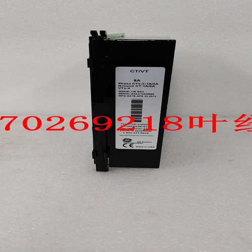
IS200HFPAG1工控模块卡件
状态指示器:每点开或关状态1状态指示器:模块状态通过、故障、,有源点隔离:3636R 1500 VDC最小点隔离:3.636T 2500 VDC最小逻辑功率:所有点关闭<10瓦逻辑功率:全部点打开<20瓦120第2章Tricon v9–v10系统24 VDC双数字输出模块系统组件规划和安装指南此图为3664和3674型数字输出模块的简化示意图。图50 3664和3674简化示意图总线XcvrμProc点寄存器总线Xcvr点寄存器总线Xcvr点寄存器环回检测器/隔离器A B C三重I/O总线智能I/O控制器(S)现场电路典型点(32)–表决输出驱动电路表决输出驱动电路PWR负载RTN*所有输出开关均为光学隔离。**到其他点到其他点μProcμProc数字输出模块121 Tricon v9–v10系统的规划和安装指南此图显示了3664和3674型的前面板。图51 Tricon v9–v10系统3664和3674前面板和安装指南3664和3684规格本表列出了3664和3664型号的规格,它们是标称电压范围为24 VDC的双数字输出模块。注:3664和3674型不建议用于通电跳闸应用,因为特定硬件故障可能导致其输出卡在关闭(断电)状态。表45 3664和3674双数字输出规格特性规格颜色代码深蓝色输出信号数量32,通用输出配置双,串行推荐电压范围16–30 VDC最大电压36 VDC逻辑功率<10瓦额定电流,最大2安培/点,10安培浪涌/10 ms负载漏电流2 mA,最大保险丝(现场终端)不需要;输出开关对过电压、过温度和过电流进行自我保护状态指示器:开或关状态每点1个状态指示器:模块状态通过、故障、活动状态指示器:现场报警1负载/保险丝点隔离最小1500 VDC诊断故障持续时间最大2 ms,500μs典型输出诊断故障范围3:最大输出切换率最小输出切换率每100毫秒加一次扫描不需要故障条件下的输出行为4::故障前的输出值指令状态开或关故障后的输出值命令状态开或关闭故障后的输出值指令状态关或关故障时的输出值5关(断电)所有其他故障后的值现场故障条件下的命令状态开或关输出行为:负载报警,输出卡在开:(3664型)卡点开,所有其他命令状态开/关负载报警,所有其他输出卡在打开:(3674型)卡点开,其他所有关闭(断电)数字输出模块123 Tricon v9–v10系统负载报警规划和安装指南,输出卡在关闭状态:(型号3664和3674)卡在关闭位置,所有其他命令状态打开或关闭打开状态电压降:在背板上<0.5 VDC典型@500mA<0.5 VDC最大@2A打开状态电压下降:带外部终端,10英尺电缆<1.5 VDC典型@500 mA<2.5 VDC最大@2 A打开状态电压降低:带外部端接,99英尺电缆<3.5 VDC典型@500mA<8.5 VDC最大@2A感应反冲保护(反EMF)输出开关为自我保护1。必须向所有点供电,包括非公用面板上未使用的点。2.可使用OVD禁用功能禁用诊断故障。3.最大输出切换率可实现I/O诊断的正确操作和所有正常可检测故障的检测。
Status indicator: On or Off state 1 per point Status indicator: Module status Pass, Fault, Active Point isolation: 3636R 1500 VDC minimum Point isolation: 3636T 2500 VDC minimum Logic power: All points Off < 10 watts Logic power: All points On < 20 watts 120 Chapter 2 System Components Planning and Installation Guide for Tricon v9–v10 Systems 24 VDC Dual Digital Output Modules This figure is a simplified schematic for models 3664 and 3674, which are Digital Output Modules. Figure 50 3664 and 3674 Simplified Schematic Bus Xcvr μProc Point Register Bus Xcvr Point Register Bus Xcvr Point Register Loopback Detector/ Isolator A B C TRIPLICATED I/O BUS INTELLIGENT I/O CONTROLLER(S) FIELD CIRCUITRY TYPICAL POINT (32) – Voted Output Drive Circuitry Voted Output Drive Circuitry PWR LOAD RTN * All output switches are optically isolated. * * To Other Points To Other Points μProc μProc Digital Output Modules 121 Planning and Installation Guide for Tricon v9–v10 Systems This figure shows the front panels of models 3664 and 3674. Figure 51 3664 and 3674 Front Panels ing and Installation Guide for Tricon v9–v10 Systems 3664 and 3674 Specifications This table lists the specifications for models 3664 and 3674, which are Dual Digital Output Modules with a nominal voltage range of 24 VDC. Note Models 3664 and 3674 are not recommended for use in energize-to-trip applications because specific hardware faults may cause its outputs to be stuck-Off (de-energized). Table 45 3664 and 3674 Dual Digital Output Specifications Feature Specification Color code Dark blue Number of output signals 32, commoned Output Configuration Dual, serial Recommended voltage range 16–30 VDC Maximum voltage 36 VDC Logic power < 10 watts Current ratings, maximum 2 amps/point, 10 amps surge/10 ms Leakage current to load 2 mA, maximum Fuses (field termination) Not required; output switches are self-protected against over-voltage, over-temperature, and overcurrent Status indicator: On or Off state 1 per point Status indicator: Module status Pass, Fault, Active Status indicator: Field alarm1 Load/fuse Point isolation 1500 VDC minimum Diagnostic glitch duration2 2 ms maximum, 500 μs typical Output diagnostic fault coverage3: Maximum output toggle rate Minimum output toggle rate Every 100 ms plus one scan Not required Output behavior under fault conditions4:: Output value before fault Commanded state—On or Off Output value after stuck-On fault Commanded state—On or Off Output value after stuck-Off fault5 Off (de-energized) Output value after all other faults Commanded state—On or Off Output behavior under field fault conditions: Load alarm, output stuck-On: (model 3664) Stuck point On, all others commanded state—On or Off Load alarm, output stuck-On: (model 3674) Stuck point On, all others Off (de-energized) Digital Output Modules 123 Planning and Installation Guide for Tricon v9–v10 Systems Load alarm, output stuck-Off: (models 3664 and 3674) Stuck point Off, all others commanded state—On or Off On-state voltage drop: At backplane < 0.5 VDC typical @ 500mA < 0.5 VDC maximum @ 2A On-state voltage drop: With external termination, 10-foot cable < 1.5 VDC typical @ 500mA < 2.5 VDC maximum @ 2A On-state voltage drop: With external termination, 99-foot cable < 3.5 VDC typical @ 500mA < 8.5 VDC maximum @ 2A Inductive kick-back protection (reverse EMF) Output switches are self-protected 1. Power must be supplied to all points, including unused points on non-commoned panels. 2. Diagnostic glitching can be disabled by using the OVD disable function. 3. The maximum output toggle rate enables proper operation of I/O diagnostics and detection of all normally detectable faults.


