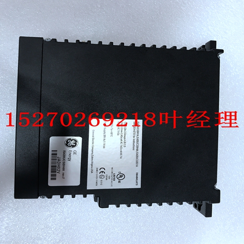
IS200ICBDH1BAA机器人模块卡件
故障条件下的行为3:输入值,500 ms关闭后,断电1。最大输入切换率可实现I/O诊断的正确操作和所有正常可检测故障的检测。最小切换率提供了模块计算平均故障间隔时间(MTBF)10%内正常不可检测故障的故障覆盖率。2.VIN是励磁电压。在诊断故障持续期间,输出电压在断开输入点的励磁电路上很明显。请注意,故障输出可能会错误地激励另一台设备的并联输入。3.单个DI模块的每个通道每500毫秒独立地对每个输入点执行一组完整的诊断。检测到故障后,每个通道向主处理器报告未通过100%诊断测试的每个点为关闭。非冗余输入电路中的故障影响所有三个通道报告的值,而仅影响一个通道的故障仅影响该通道报告的数值。表29 3564数字输入规格(续)功能规格数字输出模块87 Tricon v9–v10系统数字输出模块规划和安装指南本节介绍了可用于Tricon v9-v10系统的数字输出模块,包括TMR和单(非三重)模块。有关现场接线信息,请参阅第192页的数字输出现场接线注意事项。每个数字输出模块包含三个相同的隔离通道的电路。每个通道包括一个I/O微处理器,该微处理器从其相应主处理器上的I/O通信处理器接收其输出表。除双DC模块外,所有数字输出模块都使用特殊的四倍输出电路,在将输出信号施加到负载之前对单个输出信号进行表决。该表决器电路基于并联-串联路径,如果通道A和B、通道B和C或通道A和C的驱动器命令它们闭合,即三选二的驱动器进行表决。双数字输出模块提供单个并联或串联路径,三选二表决过程分别应用于每个开关。四倍输出电路为所有关键信号路径提供多重冗余,确保安全性和最大可用性。双输出模块提供了足够的冗余以确保安全操作。双模块针对低成本比最大可用性更重要的安全关键应用进行了优化。表30数字输出模块型号电压类型3601E/T 115 VAC 16点TMR,非公用3603B 120 VDC 16点TMR、非公用3603E/T 120 VDC 16点TMR、公用3604E 24 VDC 16点TMR、非公用36007E 48 VDC 16点TPM、非公用3611E 115 VAC 8点TMR、公用3613E 120 VDC 8点TMR,公共3615E 24 VDC 8点TMR监控,低功耗,公共3617E 48 VDC 8点三元模块冗余监控,公共3623/T 120 VDC 16点三元模冗余监控,公用3624 24 VDC 16点四元模块冗余监管,公共36251 1。3625模块只能安装在Tricon v10.2及更高版本的系统中。24 VDC 32点TMR监控/非监控,通用3636R/T继电器,NO 32点非三联,非通用3664 24 VDC 32点双输出,通用3674 24 VDC 32点双输出,公共88第2章Tricon v9–v10系统数字输出模块的系统组件规划和安装指南包括热备盘功能,允许在线更换故障模块。与所有I/O模块一样,数字输出模块需要一个单独的现场终端组件,该组件带有到Tricon控制器背板的电缆接口。每个模块都采用机械键控,以防止在配置的机箱中安装不当。数字输出模块设计用于向现场设备提供电流。现场电源必须连接到现场终端模块上的每个输出点。OVD(输出表决器诊断)每种类型的数字输出模块对每个点执行特定类型的输出表决器。一般来说,在OVD执行期间,每个点的命令状态在一个输出驱动器上立即反转,一个接一个。模块上的回路允许每个微处理器读取该点的输出值,以确定输出电路中是否存在潜在故障。因为OVD强制模拟故障,所以它会干扰附加的负载。
behavior under fault conditions3: Input value, after 500 ms Off, de-energized 1. The maximum input toggle rate enables proper operation of I/O diagnostics and detection of all normally detectable faults. The minimum toggle rate provides fault coverage of normally undetectable faults within 10% of the calculated mean-time-between-faults (MTBF) for the module. 2. VIN is the field voltage. Output voltage is noticeable on the field circuit of an Off input point for the duration of the diagnostic glitch. Be advised that the glitched output may falsely energize the paralleled input of another piece of equipment. 3. Each channel of the Single DI module independently performs a complete set of diagnostics on each input point every 500 milliseconds. Upon detection of a fault, each point which does not pass 100% of the diagnostic tests is reported as Off to the Main Processor by each channel. Faults in the nonredundant input circuitry affect the value reported by all three channels, whereas faults that affect only one channel affect only the value reported by that channel. Table 29 3564 Digital Input Specifications (continued) Feature Specification Digital Output Modules 87 Planning and Installation Guide for Tricon v9–v10 Systems Digital Output Modules This section describes the Digital Output Modules available for use with Tricon v9–v10 systems, which include TMR and Single (non-triplicated) modules. For field wiring information, see Digital Output Field Wiring Precautions on page 192. Each Digital Output Module houses the circuitry for three identical, isolated channels. Each channel includes an I/O microprocessor which receives its output table from the I/O communication processor on its corresponding Main Processor. All the Digital Output Modules, except the dual DC modules, use special quadruplicated output circuitry which votes on the individual output signals just before they are applied to the load. This voter circuitry is based on parallel-series paths which pass power if the drivers for Channels A and B, or Channels B and C, or Channels A and C command them to close—in other words, 2-out-of-3 drivers voted On. The dual Digital Output Modules provide a single parallel or series path, with the 2-out-of-3 voting process applied individually to each switch. The quadruplicated output circuitry provides multiple redundancy for all critical signal paths, guaranteeing safety and maximum availability. The dual output module provides just enough redundancy to ensure safe operation. Dual modules are optimized for those safety-critical applications where low cost is more important than maximum availability. Table 30 Digital Output Modules Model Voltage Type 3601E/T 115 VAC 16-point TMR, Non-Commoned 3603B 120 VDC 16-point TMR, Non-Commoned 3603E/T 120 VDC 16-point TMR, Commoned 3604E 24 VDC 16-point TMR, Non-Commoned 3607E 48 VDC 16-point TMR, Non-Commoned 3611E 115 VAC 8-point TMR Supervised, Commoned 3613E 120 VDC 8-point TMR Supervised, Commoned 3614E 24 VDC 8-point TMR Supervised, Commoned 3615E 24 VDC 8-point TMR Supervised, Low Power, Commoned 3617E 48 VDC 8-point TMR Supervised, Commoned 3623/T 120 VDC 16-point TMR Supervised, Commoned 3624 24 VDC 16-point TMR Supervised, Commoned 36251 1. The 3625 module can be installed only in Tricon v10.2 and later systems. 24 VDC 32-point TMR Supervised/Non-Supervised, Commoned 3636R/T Relay, NO 32-point Non-Triplicated, Non-Commoned 3664 24 VDC 32-point Dual Output, Commoned 3674 24 VDC 32-point Dual Output, Commoned 88 Chapter 2 System Components Planning and Installation Guide for Tricon v9–v10 Systems Digital Output Modules include the hot-spare feature which allows online replacement of a faulty module. Like all I/O modules, Digital Output Modules require a separate field termination assembly with a cable interface to the Tricon controller backplane. Each module is mechanically keyed to prevent improper installation in a configured chassis. Digital Output Modules are designed to source the current to field devices. Field power must be wired to each output point on a field termination module. OVD (Output Voter Diagnostics) Each type of Digital Output Module executes a particular type of Output Voter Diagnostic for every point. In general, during OVD execution the commanded state of each point is momentarily reversed on one of the output drivers, one after another. Loop-back on the module allows each microprocessor to read the output value for the point to determine whether a latent fault exists within the output circuit. Because OVD forces a simulated failure, it glitches the attached load.


