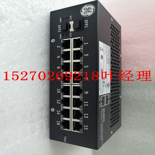
IS200IHG1A工业卡件,ABB卡件
Tricon v9–v10系统64点单端模拟输入模块规划和安装指南本图为3704E型的简化示意图,该型号为64点TMR模拟输入模块。图22 3704E简化示意图1。快速或连续变化的输入可能会导致错误比较读数,因为三个通道的测量值可能相差满量程的0.5%以上,这可能会导致故障被宣布为错误。如果输入读数至少相差满量程的0.5%,并且至少持续256个输入样本,则故障概率增加。总线Xcvr总线XcvrBus Xcvr A B C ADC单个点场终端隔离/滤波每个支路的单个ADC智能I/O控制器(S)三重I/O总线信号调节模拟输入电路–典型点(64个中的1个)Amp Mux Amp MuxAmp Mux-Amp Hi-Ref Lo-Ref Hi-Ref Hi-Ref Lo-Ref-Lo-Ref ADCμProcμProc模拟输入模块57规划和安装指南Tricon v9–v10系统本图为3720型的简化示意图,该型号为64点TMR模拟输入模块,具有现场到系统隔离。图23 3720简化示意图总线Xcvr总线Xcvr-总线XcvrA B C ADC单个点场终端隔离/滤波每个支路智能I/O控制器的单个ADC三重I/O总线信号调节模拟输入电路-典型点(64个中的1个)Amp Mux Amp Mux-Amp Mux-Amp MuxHi-Ref Hi-Ref Lo-Ref Hi-Ref Lo-RefADCμProcμProc Isol。隔离。隔离。58第2章Tricon v9–v10系统的系统组件规划和安装指南此图显示了3704E和3720型的前面板。图24 3704E和3720前面板铜带HDAI 3704E 0-5或0-10 VDC PASS FAULT ACTIVE黄色条纹模拟输入3720 0-5 VDC PASSFAULT ACTIVE FIELD模拟输入模块59 Tricon v9–v10系统3704E规范规划和安装指南本节包括3704E型规范,其是具有0至5 VDC或0至10 VDC电压范围的TMR模拟输入模块。表16 3704E模拟输入规格特性规格颜色代码铜输入信号数量64,通用,DC耦合输入更新率75ms分辨率12位精度<FSR的0.25%,从0°C到60°C输入电阻(负载)30 MΩ(DC)最小电源关闭时输入电阻30 kΩ(DC,0至5.3 VDC或0至10.6 VDC逻辑功率<10瓦输入超范围保护150 VDC连续;115 VAC连续输入范围电流0至20 mA,带250或500Ω分流电阻器模块状态指示灯通过、故障、激活输入诊断故障范围1最小输入变化输入变化采样周期最小误比较周期1。快速或连续变化的输入可能会导致错误比较读数,因为三个通道的测量值可能相差满量程的0.5%以上,这可能会导致故障被宣布为错误。如果输入读数至少相差满量程的0.5%,并且至少持续256个输入样本,则故障概率增加。满量程1次扫描的0.5%或50 ms(以较大者为准)256个样本60第2章Tricon v9–v10系统3720规格的系统组件规划和安装指南本节包括3720型号的规格,该型号为TMR模拟输入模块,电压范围为0至5 VDC。3720模块只能安装在Tricon v10.2及更高版本的系统中。注意3720可以安装在已升级到v10.2.x或更高版本的低密度系统中。有关更多信息,请参阅Tricon v9–v10系统现场终端指南中的附录I“低密度机箱I/O模块兼容性”。表17 3720模拟输入规格特性规格颜色代码黄色输入信号数量64,单端输入更新率10 ms分辨率12位或14位可编程精度<0°至60°C FSR的0.15%输入电阻(负载)10 MΩ(DC),断电时最小输入电阻140 kΩ(DC,典型正常模式抑制-3 dB@8 Hz-17 dB@60 Hz-23 dB@120 Hz输入电压范围0至5 VDC输入超范围测量+6%,0至5.3 V,0至10.6V逻辑功率<12瓦输入超范围保护150 VDC连续,115 VAC连续输入电流范围0至20 mA(超出范围加上6%),带250Ω分流电阻器现场至系统隔离800 VDC最小模块状态指示灯通过、故障、激活、现场输入诊断故障覆盖范围1最小输入变化输入变化采样周期最小误比较周期1。快速或连续改变输入可能会导致检测故障的时间增加。如果输入Planning and Installation Guide for Tricon v9–v10 Systems 64-Point Single-Ended Analog Input Modules This figure is a simplified schematic for model 3704E, which is a 64-point TMR Analog Input Module. Figure 22 3704E Simplified Schematic 1. Rapidly or continuously changing inputs may cause mis-compare readings because the measured values of the three channels may different by more than 0.5 percent of full scale, which can cause a fault to be declared in error. If the input readings differ by a minimum of 0.5 percent of full scale and continue for a minimum period of 256 input samples, the probability of a fault increases. Bus Xcvr Bus Xcvr Bus Xcvr A B C ADC Individual Point Field Terminations Isolation/ Filtering INDIVIDUAL ADC FOR EACH LEG INTELLIGENT I/O CONTROLLER(S) TRIPLICATED I/O BUS SIGNAL CONDITIONING ANALOG INPUT CIRCUIT – TYPICAL POINT (1 of 64) Amp Mux Amp Mux Amp Mux Hi Ref Lo Ref Hi Ref Lo Ref Hi Ref Lo Ref ADC ADC μProc μProc μProc Analog Input Modules 57 Planning and Installation Guide for Tricon v9–v10 Systems This figure is a simplified schematic for model 3720, which is a 64-point TMR Analog Input Module with field-to-system isolation. Figure 23 3720 Simplified Schematic Bus Xcvr Bus Xcvr Bus Xcvr A B C ADC Individual Point Field Terminations Isolation/ Filtering INDIVIDUAL ADC FOR EACH LEG INTELLIGENT I/O CONTROLLER(S) TRIPLICATED I/O BUS SIGNAL CONDITIONING ANALOG INPUT CIRCUIT – TYPICAL POINT (1 of 64) Amp Mux Amp Mux Amp Mux Hi Ref Lo Ref Hi Ref Lo Ref Hi Ref Lo Ref ADC ADC μProc μProc μProc Isol. Isol. Isol. 58 Chapter 2 System Components Planning and Installation Guide for Tricon v9–v10 Systems This figure shows the front panels of models 3704E and 3720. Figure 24 3704E and 3720 Front Panels Copper Stripe HDAI 3704E 0-5 or 0-10 VDC PASS FAULT ACTIVE Yellow Stripe ANALOG INPUT 3720 0-5 VDC PASS FAULT ACTIVE FIELD Analog Input Modules 59 Planning and Installation Guide for Tricon v9–v10 Systems 3704E Specifications This section includes specifications for model 3704E, which is a TMR Analog Input Module with a voltage range of 0 to 5 VDC or 0 to 10 VDC. Table 16 3704E Analog Input Specifications Feature Specification Color code Copper Number of input signals 64, commoned, DC-coupled Input update rate 75 ms Resolution 12 bits Accuracy < 0.25% of FSR, from 0° to 60° C Input resistance (load) 30 MΩ (DC) minimum Input resistance @ power off 30 kΩ (DC) typical Channel-to-channel isolation 200 kΩ typical Normal mode rejection -1 dB @ 8 Hz -12 dB @ 60 Hz -18 dB @ 120 Hz Input range voltage 0 to 5 VDC or 0 to 10 VDC, (configured in TriStation) Input over-range measurement +6%, 0 to 5.3 VDC or 0 to 10.6 VDC Logic power < 10 watts Input over-range protection 150 VDC continuous; 115 VAC continuous Input range current 0 to 20 mA with 250 or 500 Ω shunt resistor Module status indicators Pass, Fault, Active Input diagnostic fault coverage1 Minimum input change Input change sample period Minimum period of mis-compares 1. Rapidly or continuously changing inputs may cause mis-compare readings because the measured values of the three channels may different by more than 0.5 percent of full scale, which can cause a fault to be declared in error. If the input readings differ by a minimum of 0.5 percent of full scale and continue for a minimum period of 256 input samples, the probability of a fault increases. 0.5% of full scale 1 scan or 50 ms, whichever is greater 256 samples 60 Chapter 2 System Components Planning and Installation Guide for Tricon v9–v10 Systems 3720 Specifications This section includes specifications for model 3720, which is a TMR Analog Input Module with a voltage range of 0 to 5 VDC. The 3720 module can be installed only in Tricon v10.2 and later systems. Note The 3720 can be installed in low-density systems that have been upgraded to v10.2.x or later. For more information, see Appendix I, Low-Density Chassis I/O Module Compatibility in the Field Terminations Guide for Tricon v9–v10 Systems. Table 17 3720 Analog Input Specifications Feature Specification Color code Yellow Number of input signals 64, single-ended Input update rate 10 ms Resolution 12 bits or 14 bits programmable Accuracy < 0.15% of FSR from 0° to 60° C Input resistance (load) 10 MΩ (DC), minimum Input resistance at power off 140 kΩ (DC), typical Channel-to-channel isolation 420 kΩ, typical Normal mode rejection -3 dB @ 8 Hz -17 dB @ 60 Hz -23 dB @ 120 Hz Input voltage range 0 to 5 VDC Input over-range measurement +6%, 0 to 5.3 V, 0 to 10.6V Logic power < 12 watts Input over-range protection 150 VDC continuous, 115 VAC continuous Input current range 0 to 20 mA (plus 6% over-range) with 250 Ω shunt resistor Field to system isolation 800 VDC minimum Module status indicators Pass, Fault, Active, Field Input diagnostic fault coverage1 Minimum input change Input change sample period Minimum period of mis-compares 1. Rapidly or continuously changing inputs may cause the time to detect a fault to increase. If an input sample changes by more that 0.25% from the previous sample the readings will not be compared.


