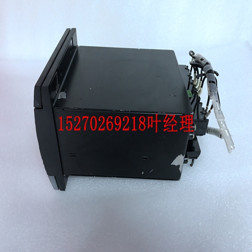
IS200ISBDG1AAA IS200ISBDG1模块DCS工控模块备件
锁定并返回。根据WDT控制状态寄存器(CSR2)中“读取锁存选择”位的设置,有两种模式决定如何锁存计数。有关这两种模式的更多信息,请参阅CSR2寄存器说明。定时器1 IRQ清除(T1IC)定时器1 IRQ-清除(T1IC)寄存器用于清除定时器1引起的中断。写入此寄存器(位于BAR2中地址的偏移量0x30处),将清除计时器1的中断。这也可以通过将“0”写入定时器控制状态寄存器的相应“定时器x引起的IRQ”字段来完成。该寄存器是只读的,写入的数据是无关的。定时器2 IRQ清除(T2IC)定时器2 IRQ-清除(T2IC)寄存器用于清除定时器2引起的中断。写入此寄存器(位于BAR2中地址的偏移量0x34处)会导致定时器2的中断被清除。这也可以通过将“0”写入定时器控制状态寄存器的相应“定时器x引起的IRQ”字段来完成。该寄存器是只读的,写入的数据是无关的。定时器3 IRQ清除(T3IC)定时器3 IRQ-清除(T3IC)寄存器用于清除定时器3引起的中断。写入此寄存器(位于BAR2中地址的偏移量0x38处)会导致计时器3的中断被清除。这也可以通过将“0”写入定时器控制状态寄存器的相应“定时器x引起的IRQ”字段来完成。该寄存器是只读的,写入的数据是无关的。字段位读取或写入计时器4计数TMRCCR4[31..0]R.O.62 3 VMIVME-7750产品手册计时器4 IRQ清除(T4IC)计时器4 IRQ-清除(T4IC)寄存器用于清除计时器4引起的中断。写入此寄存器(位于BAR2中地址的偏移量0x3C处),将清除定时器4的中断。这也可以通过将“0”写入定时器控制状态寄存器的相应“定时器x引起的IRQ”字段来完成。该寄存器是只读的,写入的数据是无关的。63看门狗定时器3看门狗定时器概述VMIVME-7750提供了一个可编程看门狗定时器(WDT),如果软件完整性失败,可以使用它来重置系统。WDT控制状态寄存器(WCSR)WDT由位于BAR2地址偏移0x08处的WDT控制状况寄存器(WCS)控制和监控。此寄存器中的位映射如下:“WDT超时选择”字段用于选择看门狗定时器的超时值,如下所示:“SERR/RST选择”位用于选择WDT是否在本地PCI总线上生成SERR#或系统重置。如果该位设置为“0”,WDT将生成系统重置。否则,WDT将激活本地PCI总线SERR#信号。字段位读取或写入SERR/RST选择WCSR[16]R/W WDT超时选择WCSR[10..8]R/W WDR启用WCSR[0]R/W所有这些位在系统重置后默认为“0”。保留所有其他位。超时WCSR[10]WCSR[9]WCSR[8]135s 0 0 0 33.6s 0 0 1 2.1s 0 1 0 524ms 0 1 1 262ms 1 0 131ms 1 0 1 32.768ms 1 1 0 2.048ms 1 1 1 64 3 VMIVME-7750产品手册“WDT启用”位用于启用看门狗定时器功能。此位必须设置为
latched and returned. There are two modes that determine how the count is latched depending on the setting of the “Read Latch Select” bit in the WDT Control Status Register (CSR2). See the CSR2 register description for more information on these two modes. Timer 1 IRQ Clear (T1IC) The Timer 1 IRQ Clear (T1IC) register is used to clear an interrupt caused by Timer 1. Writing to this register, located at offset 0x30 from the address in BAR2, causes the interrupt from Timer 1 to be cleared. This can also be done by writing a “0” to the appropriate “Timer x Caused IRQ” field of the timer Control Status Register . This register is write only and the data written is irrelevant. Timer 2 IRQ Clear (T2IC) The Timer 2 IRQ Clear (T2IC) register is used to clear an interrupt caused by Timer 2. Writing to this register, located at offset 0x34 from the address in BAR2, causes the interrupt from Timer 2 to be cleared. This can also be done by writing a “0” to the appropriate “Timer x Caused IRQ” field of the timer Control Status Register . This register is write only and the data written is irrelevant. Timer 3 IRQ Clear (T3IC) The Timer 3 IRQ Clear (T3IC) register is used to clear an interrupt caused by Timer 3. Writing to this register, located at offset 0x38 from the address in BAR2, causes the interrupt from Timer 3 to be cleared. This can also be done by writing a “0” to the appropriate “Timer x Caused IRQ” field of the timer Control Status Register . This register is write only and the data written is irrelevant. Field Bits Read or Write Timer 4 Count TMRCCR4[31..0] R.O. 62 3 VMIVME-7750 Product Manual Timer 4 IRQ Clear (T4IC) The Timer 4 IRQ Clear (T4IC) register is used to clear an interrupt caused by Timer 4. Writing to this register, located at offset 0x3C from the address in BAR2, causes the interrupt from Timer 4 to be cleared. This can also be done by writing a “0” to the appropriate “Timer x Caused IRQ” field of the timer Control Status Register . This register is write only and the data written is irrelevant. 63 Watchdog Timer 3 Watchdog Timer General The VMIVME-7750 provides a programmable Watchdog Timer (WDT) which can be used to reset the system if software integrity fails. WDT Control Status Register (WCSR) The WDT is controlled and monitored by the WDT Control Status Register (WCSR) which is located at offset 0x08 from the address in BAR2. The mapping of the bits in this register are as follows: The “WDT Timeout Select” field is used to select the timeout value of the Watchdog Timer as follows: The “SERR/RST Select” bit is used to select whether the WDT generates an SERR# on the local PCI bus or a system reset. If this bit is set to “0”, the WDT will generate a system reset. Otherwise, the WDT will make the local PCI bus SERR# signal active. Field Bits Read or Write SERR/RST Select WCSR[16] R/W WDT Timeout Select WCSR[10..8] R/W WDT Enable WCSR[0] R/W All of these bits default to “0” after system reset. All other bits are reserved. Timeout WCSR[10] WCSR[9] WCSR[8] 135s 0 0 0 33.6s 0 0 1 2.1s 0 1 0 524ms 0 1 1 262ms 1 0 0 131ms 1 0 1 32.768ms 1 1 0 2.048ms 1 1 1 64 3 VMIVME-7750 Product Manual The “WDT Enable” bit is used to enable the Watchdog Timer function. This bit must be set to


