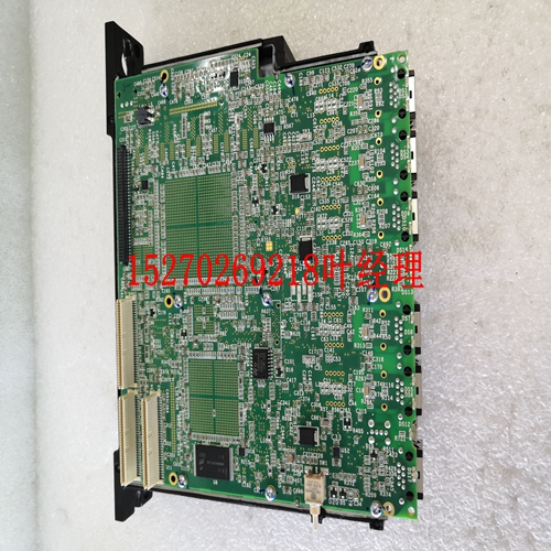
IS200JPDFG1A工控模块系统备件
根据VMEbus规范。表1-4出厂配置-BIOS写保护-跳线(E6)选择跳线位置写保护输入未写保护输出表1-5 VME跳线(用户可配置)-跳线(E12)选择跳线映射UNIV2到I/O空间1-3启用SYSFAIL生成2-4表1-6 VME跳线2-4表1-7 VME跳线(用户可配置)-跳线(E13)选择跳线位置启用VME SYSRESET驱动器1-3启用SYSRESET接收器2-4 30 1 VMIVME-7750产品手册安装VMIVME-7740符合单槽6U双Eurocard(双高度)的VMEbus物理规范。它可以直接插入任何接受这种类型板的标准机箱。小心:通电时,请勿安装或卸下电路板。以下步骤描述了VMIC推荐的VMIVME-7750安装和通电方法:1。确保设备的电源已关闭。选择机箱插槽。VMIVME-7750必须连接到双P1/P2 VME总线背板。如果VMIVME-7750将成为VMEbus系统控制器,请选择第一个VMEbus插槽。如果VMEbus系统控制器是不同的板,请选择插槽1以外的任何插槽。VMIVME-7750不需要跳线来启用/禁用系统控制器功能。注:散热器输出侧测得的空气流量要求大于350LFM。3.将所有需要的外围设备连接到前面板。每个连接器在前面板上都有清晰的标签,详细的引出线在附录A中。如果用户之前没有配置过系统,则至少需要一个键盘和一个显示器。4.接通系统电源。屏幕上显示多条消息,包括VMIVME-7750上各种BIOS模块的名称、版本和版权日期。5.VMIVME-7750的特点是板上有一个闪存磁盘。有关设置的详细信息,请参阅第4章。6.如果安装了外部驱动器模块,则必须运行BIOS设置程序来配置驱动器类型。请参阅附录C以正确配置系统。7.如果存在驱动模块,请按照制造商的说明安装操作系统。有关在操作系统安装期间安装VMIVME-7750外围驱动程序软件的说明,请参阅附录B。31安装1 BIOS设置VMIVME-7750有一个板载BIOS设置程序,可控制许多配置选项。这些选项保存在一个特殊的非易失性、电池支持的存储芯片中,统称为电路板的“CMOS配置”。CMOS配置从施加电源的那一刻起控制与硬件行为有关的许多细节。VMIVME-7750出厂时,CMOS中的硬盘驱动器类型配置设置为自动。VMIVME-7750 BIOS设置程序的详细信息包含在附录C中。32 1 VMIVME-7720产品手册图1-2在VMIVME-7780第三方PMC扩展板上安装PMC卡支架33前/后面板连接器1前/后板连接器VMIVME-7740提供前面板访问PMC扩展站点、VGA连接器、两个10/100以太网连接器、,手动复位开关、COM 1和2、双USB和状态LED。VMIVME-7750前面板的图纸如图1-3所示。前面板连接器和指示灯标记如下:•LAN 1 10/100 Mbit以太网连接器•LAN 2 10/100 Mbbit以太网连接器•SVGA SVGA视频连接器
in accordance with the VMEbus Specification. Table 1-4 Factory Configured - BIOS Write Protect - Jumper (E6) Select Jumper Position Write Protected In Not Write Protected OUT Table 1-5 VME Jumper (User Configurable) - Jumper (E12) Select Jumper Position Map UNIV2 to I/O Space 1-3 Enable SYSFAIL Generation 2-4 Table 1-6 VME Jumper (User Configurable) - Jumper (E12) Select Jumper Position Map UNIV2 to I/O Space 1-3 Enable SYSFAIL Generation 2-4 Table 1-7 VME Jumper (User Configurable) - Jumper (E13) Select Jumper Position Enable VME SYSRESET Driver 1-3 Enable SYSRESET Receiver 2-4 30 1 VMIVME-7750 Product Manual Installation The VMIVME-7750 conforms to the VMEbus physical specification for a single slot 6U dual Eurocard (dual height). It can be plugged directly into any standard chassis accepting this type of board. CAUTION: Do not install or remove the board while power is applied. The following steps describe the VMIC recommended method for VMIVME-7750 installation and power-up: 1. Make sure power to the equipment is off. 2. Choose chassis slot. The VMIVME-7750 must be attached to a dual P1/P2 VMEbus backplane. If the VMIVME-7750 is to be the VMEbus system controller, choose the first VMEbus slot. If a different board is the VMEbus system controller, choose any slot except slot one. The VMIVME-7750 does not require jumpers for enabling/disabling the system controller function. NOTE: Air flow requirements as measured at output side of heatsink is to be greater than 350LFM. 3. Connect all needed peripherals to the front panel. Each connector is clearly labeled on the front panel, and detailed pinouts are in Appendix A. Minimally, a keyboard and a monitor are required if the user has not previously configured the system. 4. Apply power to the system. Several messages are displayed on the screen, including names, versions and copyright dates for the various BIOS modules on the VMIVME-7750. 5. The VMIVME-7750 features a Flash Disk resident on the board. Refer to Chapter 4 for set up details. 6. If an external drive module is installed, the BIOS Setup program must be run to configure the drive types. See Appendix C to properly configure the system. 7. If a drive module is present, install the operating system according to the manufacturer’s instructions. See Appendix B for instructions on installing VMIVME-7750 peripheral driver software during operating system installation. 31 Installation 1 BIOS Setup The VMIVME-7750 has an on-board BIOS Setup program that controls many configuration options. These options are saved in a special non-volatile, battery-backed memory chip and are collectively referred to as the board’s ‘CMOS Configuration’. The CMOS configuration controls many details concerning the behavior of the hardware from the moment power is applied. The VMIVME-7750 is shipped from the factory with hard drive type configuration set to AUTO in the CMOS. Details of the VMIVME-7750 BIOS setup program are included in Appendix C. 32 1 VMIVME-7750 Product Manual Figure 1-2 Installing a PMC Card on the VMIVME-7750 Third Party PMC Expansion Board Standoff 33 Front/Rear Panel Connectors 1 Front/Rear Panel Connectors The VMIVME-7750 provides front-panel access to the PMC expansion site, the VGA connector, both 10/100 Ethernet connectors, the manual reset switch, COM 1 and 2, dual USB and the status LEDs. A drawing of the VMIVME-7750 front-panel is shown in Figure 1-3. The front-panel connectors and indicators are labeled as follows: • LAN 1 10/100 Mbit Ethernet connector • LAN 2 10/100 Mbit Ethernet connector • SVGA SVGA video connector


