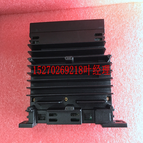
IS200F0SAG1AA模拟输入模块
联接螺母孔。以便金属耦合螺母(和屏蔽)与变频器和电机接触。l不要将导体焊接到屏蔽(猪尾巴)l使用金属夹将电机电缆的屏蔽与金属接地板连接起来。现在变频器之间有一个完美的高频接地连接。接地板和EMI滤波器。l保持变频器和EMI滤波器之间的距离尽可能短(小于30cm),否则使用带金属耦合螺母和金属夹的屏蔽电缆将屏蔽电缆连接到变频器和金属接地板。l LISN和测试板之间的唯一接地连接应通过EMI滤波器。l使用等于或低于逆变器额定功率的电机。l在主电路的输出侧安装逆变器的噪声滤波器,可抑制传导噪声(仅适用于住宅环境)。为降低无线电有源噪声,在电机和驱动器之间使用屏蔽线,该电线应与控制电线相距30 cm以上。B类,居住环境15 a级,工业环境(仅适用于内置EMC a级滤波器的驱动器,U20--S)电源部分l当逆变器和电机之间的距离超过100 m时,应仔细选择连接线,以将布线电阻降低到3%以下,电压降(V)=√3 x布线电阻(Ω/km)x电线长度(m)x电流x 10-3(B)控制电路布线必须与主电路控制线和其他高压或大电流电源线分开,以避免噪声干扰。l为了减少噪声干扰并避免错误操作,必须使用屏蔽双绞线电缆连接控制电路。请参考下图。将屏蔽线连接到接地端子上。布线距离必须小于50m。(C) 逆变器的接地端子必须正确接地,符合200V三类接地要求。l接地线应根据电气设备(AWG)接线,接地线的长度应尽可能短。l逆变器的接地线不得与其他大电流负载(如焊机或大功率电机)一起接地。它们应单独接地。屏蔽手套到逆变器端子连接到系统接地端子用绝缘胶带包裹到控制机器不要在这一端连接屏蔽线16 l将几个逆变器接地时,不得形成接地电路。良好良好不良(D)电线规格根据电力法规,为主电源电路和控制电路选择适当直径的电线。(E) 完成后,检查接线是否正确,电线是否断裂,端子螺丝是否紧固。逆变器接线图端子必须使用UL列出的现场接线接线片套件或UL列出的压接型环形端子制作注:仅适用于U20-N1K5/N2K2和U20-X0K7/X1K5/X2K2 l其他连接输出端子连接点额定容量250VAC/1A(30VDC/1A)3 FWD 4 REV操作控制端子(参考Fn_03)5+12V端子3/4/6/7 6 SP1 7重置的公共点多功能输入端子(参考Fn_19)8+10V电位计电源端子(引脚3)9模拟输入点模拟频率信号输入端子(电位计引脚2或0~110V/4~20mA/0~20mA的正极端子)10 0V(FM-)模拟公共点模拟信号公共点(电位计引脚1或0~110V/4 ~20A/0~20mA的负极端子)11 FM+模拟输出正极连接点模拟频率信号输出端子输出端子信号为0~10VDC/Fn6*TM2的拧紧力矩为0.4 Nm或5.03 LBS-IN。*200V逆变器的电线电压额定值必须至少为300V,400V逆变器的电线额定值必须为600V
coupling nut holes. So that the metal coupling nuts (and the shielding) make contact with the frequency inverter and the motor. l Don't solder a conductor to the shielding (pig tail) l Use a metal clamp to connect the shielding from the motor cable with the metal grounding plate. Now there is a perfect high frequency earth connection between frequency inverter . grounding plate and EMI filter. l Keep the distance between frequency inverter and EMI filter as short as possible ( < 30cm ) otherwise use screened cable with a metal coupling nut and a metal clamp addle to connect the shielded cable to the frequency inverter and metal grounding plate. l The only earth connection between the LISN and the test plate should be via the EMI filter. l Use a motor which equals the power rating or below of the inverter rating. l Install a noise filter for inverter onto the output side of the primary circuitry can suppress conducting noise (for residential environment only). To reduce radio active noise, use a shielded wire between motor and drive, this wiring should be away from control wiring for more than 30 cm. Class B, Residential Environment 15 Class A, Industrial Environment (only for drives with built-in EMC class A filter, U20----S) Power part l When the distance between the inverter and motor is longer than 100m, connection wire should be carefully chosen to reduce the wiring resistance below 3% and the voltage drop (V) = √ 3 x Wire resistance (Ω/km) x wire length (m) x current x 10-3 (B) Control circuitry wiring must be separated and away from the primary circuitry control line and other high-voltage or large-current power lines to avoid noise interference. l To reduce the noise interference and avoid mistake operation, shielded twisted pair cable must be used to wire the control circuitry. Please refer to following diagram. Connect the shielding wire onto the grounding terminal. Wiring distance must be under 50m. (C) The grounding terminal of the inverter must be correctly grounded in compliance with 200V class type three grounding. l Grounding wire should be wired in accordance to electrical equipment (AWG) with the length of the grounding wire as short as possible. l The grounding wire of the inverter must not be grounded together with other large current loading (such as soldering machine or large power motor). They should be grounded separately. Shielding Glove To Inverter terminal Connect to system grounding terminal Wrapped with insulating tape To control machine Do not connect the shielding wire at this end 16 l Grounding circuitry must not be formed when grounding several inverters together. Good Good Not good (D) Wire specification Choose appropriate wire with correct diameter for primary power circuitry and control circuitry in accordance with electricity regulations. (E) Upon completion, check out to reassure the wiring correctness, broken wires, and secure terminal screws. Wiring Diagram Terminations to Inverter must be made with either UL listed field wiring lug kits or UL listed crimp type ring terminals Note: only for U20-N1K5/N2K2 and U20-X0K7/X1K5/X2K2 l Other connecti output terminal Connection point rated capacity 250VAC/1A ( 30VDC / 1A ) 3 FWD 4 REV Operation control terminals (refer to Fn_03) 5 + 12V Common point of terminal 3 / 4 / 6 / 7 6 SP1 7 RESET Multifunction input terminals (refer to Fn_19) 8 +10V Power terminal of potentiometer ( Pin 3 ) 9 Analog input point Analog frequency signal input terminal ( Pin 2 of potentiometer or positive terminal of 0~10V / 4~20mA / 0~20mA) 10 0V (FM -) Analog common point Analog signal common point ( Pin 1 of potentiometer or negative terminal of 0~10V / 4~20mA / 0~20mA ) 11 FM+ Analog output positive connection point Analog frequency signal output terminal Output terminal signal is 0 ~ 10VDC/Fn6 * Tightening torque for TM2 is 0.4 Nm or 5.03 LBS-IN. * Wire voltage rating must be a minimum of 300V for 200V inverters and minimum 600V for 400V inverters * Control wiring should not run in the same conduit or race way with power or motor wiring * Single Input and Output Terminals


