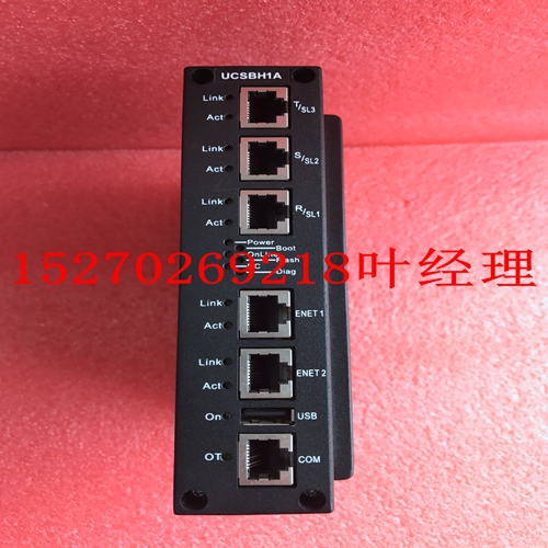
IS200FOSBH1A处理器模块
逆变器主PCB上的CMOS IC易受静电影响。不要接触逆变器的主PCB。2.安装前检查每个GE Power Controls逆变器在装运前都经过了全面测试和检查。拆开逆变器后,请执行以下检查程序。检查逆变器的型号。应该是你点的那个。检查运输过程中是否有损坏。如果有任何损坏迹象,请勿将逆变器连接到电源。如果发现上述任何异常情况,请向区域销售代表报告。4第1章。安全预防措施1.1。打开电源前的操作注意事项小心选择具有正确电压设置的适当电源作为逆变器的输入电压规格。警告:接线主电路板时必须特别小心。L1和L2端子必须连接到输入电源,并且不得错误地连接到T1、T2或T3端子。当电源打开时,这可能会损坏逆变器。小心不要试图通过前盖运输逆变器。将逆变器牢牢固定在散热器安装底盘上,以防止逆变器掉落,从而导致人员受伤或损坏逆变器。l将逆变器安装在坚固的金属底座或其他易燃材料上。请勿将逆变器安装在任何易燃材料上或附近,以免发生火灾。l如果在一个控制面板中安装了多个逆变器,则应安装额外的冷却风扇,以将内部温度降至40°以下,以避免过热或火灾报警。l在拆卸或安装操作面板之前,关闭电源。根据给出的说明执行安装程序,以避免接触不良导致操作面板故障或无显示信息。l适用于能够提供不超过5000RMS对称电流的电路,最大240V l未经超速保护或等效物证明l仅适用于污染程度2的宏观环境或等效物5当电源打开时警告l在电源打开时,请勿尝试安装或拆除逆变器的连接器。否则,逆变器可能由于插入或移除引起的浪涌峰值而损坏。l当瞬时功率损失超过2秒(马力越大,时间越长)时,逆变器没有足够的存储功率来控制电路。因此,当电源再生时,逆变器的操作基于F_10的设置和外部开关的条件,这在以下段落中被视为“重启”。l当瞬时功率损失短时,逆变器仍有足够的存储功率来控制电路;因此,当功率再生时,逆变器将根据F_23的设置再次自动启动操作。重新启动逆变器时,逆变器的操作基于F_10的设置和外部开关(FWD/REV按钮)的条件。注意:重新启动操作与F_23/F_24无关。(1) 当F_10=0时,逆变器在重新启动后不会启动。(2) 当F_10=1且外部开关(FWD/REV按钮)关闭时,逆变器在重新启动后不会启动。(3) 当F_10=1且外部开关(FWD/REV按钮)打开时,逆变器将在重启后自动启动。注意:基于安全原因,请关闭外部开关(FWD/REV按钮)
The CMOS IC on the primary PCB of the inverter is vulnerable to static electrical charges. Do not contact the primary PCB of the inverter. 2. Examination before installation Every GE Power Controls inverter has been fully tested and examined before shipment. Please carry out following examination procedures after unpacking your inverter. Check to see the model number of the inverter. It should be the one that you ordered. Check to see if there is any damage during the transportation. Do not connect the inverter to the power supply if there is any sign of damage. Report to regional sale representative if you find any abnormal condition as mentioned above. 4 Chapter 1. Safety Precautions 1.1. Precautions of operation Before turning ON power CAUTION Choose appropriate power source with correct voltage setting as the input voltage specification of the inverter. WARNING Special care must be taken while wiring the primary circuitry panel. The L1 and L2 terminal must be connected to input power source and must not be mistakenly connected to T1, T2 or T3 terminal. This may damage the inverter when the power is turned on. CAUTION l Do not attempt to transport the inverter by the front cover. Securely hold the inverter by the heat-sink mounting chassis to prevent the inverter from falling that may cause personnel injury or damage the inverter. l Install the inverter onto firm metal base or other inflammable material. Do not install the inverter onto or nearby any flammable material to avoid fire. l Additional cooling fan should be installed if several inverter are installed into one control panel to lower the temperature inside below 40° to avoid overheating or fire alarm. l Turn off power supply before proceeding removal or installation of operating panel. Carry out installation procedure according to instructions given to avoid poor-contact situation resulting operating panel malfunction or no displaying information. l Suitable for use on a circuit capable of delivering not more than 5000RMS symmetrical amperes, 240V maximum l Not proved with over speed Protection or equivalent l Only intended for use in a pollution degree 2 macro environment or equivalent 5 When power is turned ON WARNING l Do not attempt to install or remove connector of inverter when the power supply is turned on. Otherwise, the inverter may be damaged due to the surge peak caused by the insertion or removal. l When momentary power loss is longer than 2 seconds (the large of horse power, the longer of time), the inverter does not have enough storage power to control the circuit. Therefore, when power is regenerated, the operation of the inverter is based on the setup of F_10 and the condition of external switch, this is considered to be ‘restart’ in the following paragraphs. l When the momentary power loss is short, the inverter still has enough storage power to control the circuit; therefore, when power is regenerated, the inverter will automatically start operation again depends on the setup of F_23. When restart the inverter, the operation of the inverter is based on the setup of F_10 and the condition of external switch (FWD/REV button). Attention: the restart operation is irrelevant with F_23/F_24. (1) When F_10=0, the inverter will not start after restart. (2) When F_10=1 and the external switch (FWD/REV button) is OFF, the inverter will not start after restart. (3) When F_10=1 and the external switch (FWD/REV button) is ON, the inverter will start automatically after restart. Attention: Base on safety reason, please turn off the external switch (FWD/REV button)


