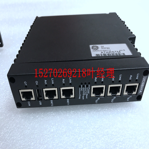
IS200GGXIG1 IS200GGXIG1AFE PLC模拟量输出模块
6701系列操作说明误差放大器将电阻R1和R2分压的电压与内部参考电压进行比较。然后,连接到VOUT引脚的P通道MOSFET由随后的输出信号驱动。VOUT引脚处的输出电压由负反馈系统控制和稳定。限流电路、短路保护电路和热保护电路的工作与输出电流和发热量有关。此外,IC的内部电路可以通过CE引脚的信号关闭。XC6701系列包括一个电流折返电路作为短路保护。当负载电流达到电流极限水平时,电流折返电路工作,输出电压下降。输出电压进一步下降,输出电流降低。当输出引脚短路时,电流约为30mA。IC的内部电路可以通过XC6701A/B系列的CE引脚的信号关闭。在关机模式下,VOUT引脚的输出将被R1和R2下拉至VSS电平。注意,由于CE引脚打开,XC6701B系列的操作将变得不稳定。我们建议您在CE引脚上使用VIN电压或VSS电压输入的IC。如果该IC与CE引脚的正确规格一起使用,则操作逻辑是固定的,IC将正常工作。然而,如果施加中等电压,由于IC内部电路中的直通电流,电源电流可能会增加。当内置驱动晶体管的结温度达到温度极限水平(150℃典型值)时,热保护电路工作,驱动晶体管将设置为OFF。当释放热关机功能时,IC恢复其操作,并且由于结温度下降到热关机释放电压的水平,IC的操作自动恢复。为了IC的稳定运行,需要超过2.0V的输入电压。如果输入电压低于2.0V,则可能无法正常产生输出电压。1.对于暂时的过渡电压降或电压上升现象,如果超过额定值,IC可能会发生故障。2.在布线阻抗较高的情况下,根据输出电流,由于噪声和/或相位滞后,操作可能变得不稳定。请特别加强VIN和VSS接线。3.在XC6701系列中执行IC内部的相位补偿。因此,即使没有输出电容器CL,也不会发生异常振荡。VIN引脚和VSS引脚之间需要0.1μF~1.0μF左右的输入电容器CIN,以确保输入稳定性。此外,可以通过在VOUT引脚和VSS引脚之间放置0.1μF~1.0μF左右的输出电容器CL来控制由于负载变化而产生的输出电压波动,如欠拍或过拍。输入电容器(CIN)和输出电容器(CL)应尽可能靠近IC,布线应更短。4.当IC无负载运行时,输出电压可能在超出运行范围的高温下增加。5.Torex重视改进我们的产品及其可靠性。然而,无论如何,我们都会要求用户对系统或设备进行故障安全设计和老化后处理。使用注意事项R1 R2 13/29 XC6701系列测试电路XC6701A/B系列XC6701D系列电路③电路①电路②XC6701A-B系列XC6700D系列XC6701AA/B系列XC6706D系列VIN VSS CE VOUT V V A IOUT Isort CIN=1uF CL=1uF(陶瓷)VIN VSS VOUT V A IOOT Isort CIN=1uF CL=1uFV~V~CL=1uF VIN VSS VOUT V~V ~ CL=1u F 14/29 XC6701 Se
6701 Series OPERATIONAL EXPLANATION The voltage divided by resistors R1 & R2 is compared with the internal reference voltage by the error amplifier. The Pchannel MOSFET, which is connected to the VOUT pin, is then driven by the subsequent output signal. The output voltage at the VOUT pin is controlled and stabilized by a system of negative feedback. The current limit circuit, short protect circuit and thermal protection circuit operate in relation to the level of output current and heat generation. Further, the IC’s internal circuitry can be shutdown via the CE pin’s signal. The XC6701 series includes a current fold-back circuit as a short circuit protection. When the load current reaches the current limit level, the current fold-back circuit operates and output voltage drops. The output voltage drops further and output current decreases. When the output pin is shorted, a current of about 30mA flows. The IC’s internal circuitry can be shutdown via the signal from the CE pin with the XC6701A/B series. In shutdown mode, output at the VOUT pin will be pulled down by R1 and R2 to the VSS level. Note that as the XC6701B series’ operations will become unstable with the CE pin open. We suggest that you use this IC with either a VIN voltage or a VSS voltage input at the CE pin. If this IC is used with the correct specifications for the CE pin, the operational logic is fixed and the IC will operate normally. However, supply current may increase as a result of through current in the IC’s internal circuitry if a medium voltage is applied. When the junction temperature of the built-in driver transistor reaches the temperature limit level (150℃ TYP.), the thermal protection circuit operates and the driver transistor will be set to OFF. The IC resumes its operation when the thermal shutdown function is released and the IC’s operation is automatically restored because the junction temperature drops to the level of the thermal shutdown release voltage. For the stable operation of the IC, over 2.0V of input voltage is necessary. The output voltage may not be generated normally if the input voltage is less than 2.0V. 1. For temporary, transitional voltage drop or voltage rising phenomenon, the IC is liable to malfunction should the ratings be exceeded. 2. Where wiring impedance is high, operations may become unstable due to the noise and/or phase lag depending on output current. Please strengthen VIN and VSS wiring in particular. 3. Phase compensation inside the IC is performed in the XC6701 series. Therefore, an abnormal oscillation does not occur even if there is no output capacitor CL. An input capacitor CIN around 0.1μF~1.0μF between the VIN pin and the VSS pin is required for input stability. Also, the output voltage fluctuation such as under shoot or over shoot, which occurs because of the load change can be controlled by placing the output capacitor CL around 0.1μF~1.0μF between the VOUT pin and VSS pin. The input capacitor (CIN) and the output capacitor (CL) should be placed to the IC as close as possible with a shorter wiring. 4. When the IC is operated with no load, the output voltage may increase in the high temperature beyond operating range. 5. Torex places an importance on improving our products and its reliability. However, by any possibility, we would request user fail-safe design and post-aging treatment on system or equipment. NOTES ON USE R1 R2 13/29 XC6701 Series TEST CIRCUITS XC6701A/B Series XC6701D Series Circuit ③ Circuit ① Circuit ② XC6701A/B Series XC6701D Series XC6701A/B Series XC6701D Series VIN VSS CE VOUT V V V A IOUT Ishort CIN=1uF CL=1uF (Ceramic) (Ceramic) VIN VSS VOUT V V A IOUT Ishort CIN=1uF CL=1uF (Ceramic) (Ceramic) VIN VSS CE VOUT A A OPEN CIN=1uF VIN VSS A VOUT OPEN CIN=1uF VIN VSS CE VOUT V ~ V ~ CL=1uF VIN VSS VOUT V ~ V ~ CL=1uF 14/29 XC6701 Se


