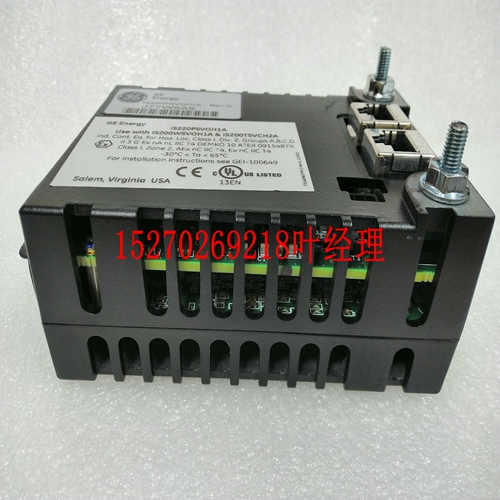
IS200HFPAG2ADC IS200HFPAG2模块控制器
模拟输入数据的参考参数返回字节长度,与活动通道的数量无关。低报警限值和高报警限值每个输入通道可以具有低报警限和高报警极限。如果输入达到其限值之一,模块将报告实际值并在故障表中报告报警故障。报警不会停止过程或更改输入值。可以在信号动态范围内的任何位置设置报警限值。每个值的范围为-32768到+32767。高报警限值必须大于低报警限值。如果不需要报警报告,则可以将报警限值设置在信号的动态范围之外,这样它们就不会被激活。热电偶限值下表列出了适用热电偶类型的毫伏和温度限值。TC型低mV限值高mV限值低温限值((C)高温限值(C)J–8.0960 57.9420–210.00 1000.00 K–5.8910 54.8069–200.00 1370.00 T–5.6030 20.2520–200.00 390.00 S–0.1940 18.5040–40.00 1750.00 R–0.1880 20.8780–40.00 175.00 GFK-1504N第14章温度传感模块14-15 14 IC200ALG630模拟输入,16位热电偶,7通道冷端补偿热电偶模块为冷端补偿提供四种选择。无冷接点补偿:这用于毫伏输入或冷接点保持在0°C。远程冷接点补偿:使用此选项,冷接点由外部测量,并通过模块的模拟输出(字输出)数据从应用程序提供给模块。如果模块有多个配置用于远程补偿的热电偶,则每个热电偶必须使用相同的补偿值。固定冷接点补偿:此选项使用以工程单位定义的固定补偿值,该值在配置参数“参考接点值”中提供。局部冷端补偿:提供局部补偿的最佳方式是插入热电偶端子。(IC200CHS014),内置热敏电阻。使用插入式托架可使热电偶连接件远离系统中的模块,这有助于保护热电偶连接件免受模块热量的影响。如果配置了本地冷端补偿,且未使用插入式热电偶端子装置,则必须在模块的托架上直接安装一个单独的热敏电阻。热敏电阻必须是套件#IC690ACC905中提供的热敏电阻。热敏电阻必须安装在载体的热敏电阻(+)和(–)端子上(热敏电阻本身没有(+)或(–)标记;其方向无关紧要)。注:如果选择了本地补偿,但未使用插入式热电偶端子或本地热敏电阻,则可能会报告错误温度,并在故障表中报告热敏电阻错误。量程选择模块可配置六个不同毫伏范围(+/-)中的任何一个:19.5mV、39mV、78.125mV、156.25mV、312.5mV和625mV。除最后一个外,所有输入读数均以百分之一毫伏为单位。对于625mV范围,输入单位为毫伏的十分之一。当用于读取毫伏时,热电偶
The reference parameter for the analog input data returns the byte length and is independent of the number of active channels. Low Alarm Limit and High Alarm Limit Each input channel can have a low alarm limit and a high alarm limit. If an input reaches one of its limits, the module reports the actual value and reports an alarm fault in the Fault Table. Alarms do not stop the process or change the value of the input. Alarm limits can be set anywhere over the dynamic range of the signal. The range for each is –32,768 to +32,767. The high alarm limit must be greater than the low alarm limit. If alarm reporting is not wanted, alarm limits can be set beyond the dynamic range of the signal so they will never be activated. Thermocouple Limits The following table lists millivolt and temperature limits for applicable thermocouple types. TC Type Low mV Limit High mV Limit Low Temperature Limit ((C) High Temperature Limit (C) J –8.0960 57.9420 –210.00 1000.00 K –5.8910 54.8069 –200.00 1370.00 T –5.6030 20.2520 –200.00 390.00 S –0.1940 18.5040 –40.00 1750.00 R –0.1880 20.8780 –40.00 1750.00 GFK-1504N Chapter 14 Temperature Sensing Modules 14-15 14 IC200ALG630 Analog Input, 16 Bit Thermocouple, 7 Channels Cold Junction Compensation The Thermocouple module provides four choices for Cold Junction Compensation. No Cold Junction Compensation: This is used for millivolt inputs or if cold junction is maintained at 0 °C. Remote Cold Junction Compensation: With this option, cold junction is measured externally and provided to the module from the application, via the module’s analog output (word output) data. If the module has multiple thermocouples that are configured for remote compensation, the same compensation value must be used by each. Fixed Cold Junction Compensation: This option uses a fixed compensation value, defined in engineering units, which is provided in configuration parameter Reference Junction Value. Local Cold Junction Compensation: The best way to provide local compensation is with an Interposing Thermocouple Terminals. (IC200CHS014), which has a built-in thermistor. Using an Interposing Carrier allows the thermocouple connections to be placed farther away from the modules in the system, which helps shield thermocouple connections from module heat. If Local Cold Junction Compensation is configured and an Interposing Thermocouple Terminals unit is not used, a separate thermistor must be installed directly at the module’s Carrier. The thermistor must be that supplied in kit # IC690ACC905. The thermistor must be installed at the carrier’s thermistor (+) and (–) terminals (the thermistor itself does not have (+) and (–) markings; its orientation does not matter). Note: If Local Compensation is selected but an Interposing Thermocouple Terminals or local thermistor is not used, erroneous temperatures may be reported and a thermistor error will be reported in the fault table. Range Selection The module is configurable for any of six different millivolt ranges (+/–): 19.5mV, 39mV, 78.125mV, 156.25mV, 312.5mV, and 625mV. All but the last provide input readings in hundredths of millivolts. For the 625mV range, inputs are in tenths of millivolts. When used to read millivolts, the Thermocouple


