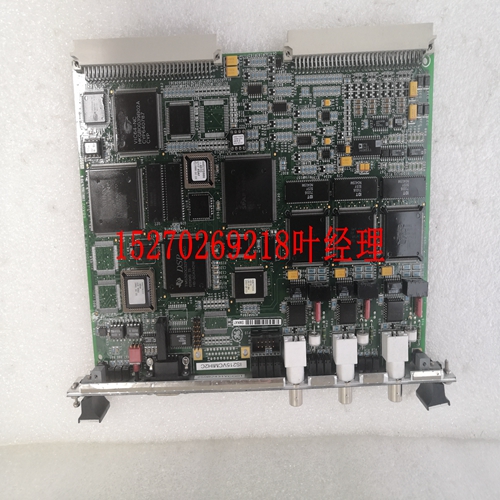
IS200ISBAH1A备件模块
数据总线6.3数据总线宽度ARM IHI 0033B。b版权所有ARM Limited或其附属公司。保留所有权利。6-65 ID102715非机密6.3数据总线宽度在不增加操作频率的情况下提高总线带宽的一种方法是使芯片上总线的数据路径更宽。金属层的增加和嵌入式DRAM等大型片上存储块的使用是鼓励使用更宽片上总线的驱动因素。指定固定的总线宽度意味着,在许多情况下,总线宽度对于应用程序来说不是最佳的。因此,已经采用了一种方法,该方法实现了总线宽度的灵活性,但仍然确保了模块在设计之间是高度可移植的。该协议允许数据总线为8、16、32、64、128、256、512或1024位宽。但是,建议使用32位的最小总线宽度。256位的最大总线宽度几乎适用于所有应用。对于读写传输,接收模块必须从总线上正确的字节通道中选择数据。不需要跨所有字节通道复制数据。以下各节描述:•在宽总线上实现窄从设备。•在第6-66页的窄总线上实现宽从站。•在第6-66页的宽总线上实现主设备。6.3.1在宽总线上实现窄从机图6-2显示了最初设计用于32位数据总线的从机模块如何转换为在64位总线上运行。这只需要添加外部逻辑,而不需要任何内部设计更改,因此该技术适用于硬宏单元。图6-2宽总线上的窄从属对于输出,当将窄总线转换为宽总线时,请执行以下操作之一:•如图6-2所示,在宽总线的两半上复制数据。•使用附加逻辑确保仅更改总线的适当一半。这导致了功耗的降低。从属设备只能接受与其自然接口一样宽的传输。如果主设备尝试的传输范围大于从设备可以支持的传输范围,则从设备可以使用ERROR传输响应。D Q EN HCLK HADDR[2]HREADY从机地址和控制HRDATA[63:32]HRDATA[31:0]HRDATA[31:0]HRADYOUT HRESP HWDATA[63:22]HWDATA[31:0]WDATA[31:0]传输响应6数据总线6.3数据总线宽度6-66版权所有ARM Limited或其附属公司。保留所有权利。ARM IHI 0033B.b非机密ID102715 6.3.2在窄总线上实现宽从机预先设计或导入的从机可以通过使用外部逻辑适应于与窄数据总线一起工作。图6-3显示了在窄总线上实现的宽从站。图6-3窄总线上的宽从设备6.3.3在宽总线上实现主设备主设备可以修改为在较宽的总线上工作,与修改从设备以在较宽总线上工作的方式相同。通过以下方式实现:•多路复用输入总线。•复制输出总线。注意:除非主设备中包含某种机制来限制主设备尝试的传输宽度,否则主设备无法在比最初预期的更窄的总线上工作。如果HSIZE指示的宽度大于连接到的数据总线,则主设备不得尝试传输。D Q EN HCLK HADDR[2]HREADY从设备地址和控制HWDATA[63:32]HWDATA[31:0]HWDATA[61:0]HREADYOUT HRESP RDATA[63:32]RDATA[31:0]HRDATA[31:0]传输响应ARM IHI 0033B。b版权所有ARM Limited或其附属公司。保留所有权利。7-67 ID102715非机密第7章时钟和复位本章描述了协议时钟和复位信号的定时。它包含以下部分:•第7-68页的时钟和重置要求。7时钟和重置7.1时钟和重置要求7-68版权所有ARM Limited或其附属公司。保留所有权利。ARM IHI 0033B.b非机密ID102715 7.1时钟和复位要求本节描述了实现HCLK和HRESETn信号的要求。7.1.1时钟每个组件使用单个时钟信号HCLK。所有输入信号在HCLK的上升沿上采样。所有输出信号变化必须发生在HCLK的上升沿之后。
Data Buses 6.3 Data bus width ARM IHI 0033B.b Copyright ARM Limited or its affiliates. All rights reserved. 6-65 ID102715 Non-Confidential 6.3 Data bus width One method to improve bus bandwidth without increasing the frequency of operation is to make the data path of the on-chip bus wider. The increased layers of metal and the use of large on-chip memory blocks such as embedded DRAM are driving factors that encourage the use of wider on-chip buses. Specifying a fixed width of bus means that, in many cases, the width of the bus is not optimal for the application. Therefore an approach has been adopted that enables flexibility of the width of bus but still ensures that modules are highly portable between designs. The protocol allows the data bus to be 8, 16, 32, 64, 128, 256, 512, or 1024-bits wide. However, it is recommended that a minimum bus width of 32 bits is used. A maximum bus width of 256 bits is adequate for almost all applications. For read and write transfers, the receiving module must select the data from the correct byte lane on the bus. Replication of data across all byte lanes is not required. The following sections describe: • Implementing a narrow slave on a wide bus. • Implementing a wide slave on a narrow bus on page 6-66. • Implementing a master on a wide bus on page 6-66. 6.3.1 Implementing a narrow slave on a wide bus Figure 6-2 shows how a slave module that has been originally designed to operate with a 32-bit data bus can be converted to operate on a 64-bit bus. This only requires the addition of external logic, rather than any internal design changes, the technique is therefore applicable to hard macrocells. Figure 6-2 Narrow slave on a wide bus For the output, when converting a narrow bus to a wider bus, do one of the following: • Replicate the data on both halves of the wide bus as Figure 6-2 shows. • Use additional logic to ensure that only the appropriate half of the bus is changed. This results in a reduction of power consumption. A slave can only accept transfers that are as wide as its natural interface. If a master attempts a transfer that is wider than the slave can support then the slave can use the ERROR transfer response. D Q EN HCLK HADDR[2] HREADY Slave Address and control HRDATA[63:32] HRDATA[31:0] HRDATA[31:0] HREADYOUT HRESP HWDATA[63:32] HWDATA[31:0] WDATA[31:0] Transfer response 6 Data Buses 6.3 Data bus width 6-66 Copyright ARM Limited or its affiliates. All rights reserved. ARM IHI 0033B.b Non-Confidential ID102715 6.3.2 Implementing a wide slave on a narrow bus Predesigned or imported slaves can be adapted to work with a narrower data bus by using external logic. Figure 6-3 shows a wide slave being implemented on a narrow bus. Figure 6-3 Wide slave on a narrow bus 6.3.3 Implementing a master on a wide bus Masters can be modified to work on a wider bus than originally intended in the same way that the slave is modified to work on a wider bus. Do this by: • Multiplexing the input bus. • Replicating the output bus. Note Masters cannot work on a narrower bus than originally intended unless some mechanism is included in the master to limit the width of transfers that the master attempts. The master must never attempt a transfer where the width, as indicated by HSIZE, is wider than the data bus that it connects to. D Q EN HCLK HADDR[2] HREADY Slave Address and control HWDATA[63:32] HWDATA[31:0] HWDATA[31:0] HREADYOUT HRESP RDATA[63:32] RDATA[31:0] HRDATA[31:0] Transfer response ARM IHI 0033B.b Copyright ARM Limited or its affiliates. All rights reserved. 7-67 ID102715 Non-Confidential Chapter 7 Clock and Reset This chapter describes the timing of the protocol clock and reset signals. It contains the following section: • Clock and reset requirements on page 7-68. 7 Clock and Reset 7.1 Clock and reset requirements 7-68 Copyright ARM Limited or its affiliates. All rights reserved. ARM IHI 0033B.b Non-Confidential ID102715 7.1 Clock and reset requirements This section describes the requirements for implementing the HCLK and HRESETn signals. 7.1.1 Clock Each component uses a single clock signal, HCLK. All input signals are sampled on the rising edge of HCLK. All output signal changes must occur after the rising edge of HCLK.


