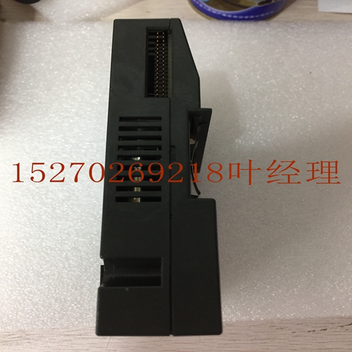
IS200ISBBG1AAB IS200ISBBG1工控模块卡件
在传输的数据阶段插入适当数量的等待状态。然后,传输完成,HREADYOUT HIGH和OKAY响应指示传输成功完成。当从设备在完成响应之前插入多个等待状态时,它必须将HRESP驱动到OKAY。表5-1 HRESP信号响应HRESP响应描述0正常传输已成功完成,或者从属设备需要额外的周期才能完成请求。HREADYOUT信号指示传输是挂起还是完成。1错误传输过程中发生错误。必须向主机发出错误条件信号,以便主机知道传输失败。当HREADYOUT在第二个周期中被断言时,错误条件需要两个周期的响应。表5-2 HRESP和HREADYOUT组合信号响应HREADYOUTHRESP 0 1 0传输挂起成功传输完成1个错误响应,第一个周期错误响应,第二个周期5个从属响应信令5.1从属传输响应ARM IHI 0033B。b版权所有ARM Limited或其附属公司。保留所有权利。5-57 ID102715非机密说明一般来说,每个从设备在完成传输之前都必须插入预定的最大等待状态数。这使得能够计算访问总线的最大延迟。建议从设备插入的等待状态不超过16个,以防止任何单个访问在大量时钟周期内锁定总线。然而,此建议不适用于某些设备,例如串行引导ROM。此类设备通常仅在系统启动期间访问,如果使用的等待状态超过16个,则对系统性能的影响可以忽略不计。5.1.3错误响应从设备使用错误响应指示相关传输的某种形式的错误状态。通常这表示一个保护错误,例如试图写入只读存储器位置。虽然可以在一个周期内给出OKAY(正常)响应,但ERROR(错误)响应需要两个周期。要启动ERROR(错误)响应,从机驱动HRESP HIGH(高)以指示ERROR(故障),同时驱动HREADYOUT LOW(低)以延长传输一个额外周期。在下一个循环中,HREADYOUT被驱动为高电平以结束传输,HRESP保持驱动为高,以指示错误。由于总线的流水线性质,需要两个周期的响应。当从设备开始发出ERROR响应时,随后传输的地址已经广播到总线上。两个周期的响应为主机提供了足够的时间来取消下一次访问,并在下一次传输开始之前将HTRANS[1:0]驱动到IDLE。如果从设备需要两个以上的周期来提供ERROR响应,则可以在传输开始时插入额外的等待状态。在此期间,HREADY为LOW(低),响应必须设置为OKAY(正常)。图5-1显示了带有ERROR响应的传输。图5-1错误响应图5-1:T1-T2从机插入等待状态并提供OK(正常)响应。T2-T3从设备发出错误响应。这是ERROR响应的第一个周期,因为HREADY为LOW。T3-T4从设备发出错误响应。这是ERROR响应的最后一个周期,因为HREADY现在为HIGH。主机将传输类型更改为IDLE。这取消了在时间T2由从设备注册的到地址B的预期事务。T4-T5从机响应
insert the appropriate number of wait states into the data phase of the transfer. The transfer then completes with HREADYOUT HIGH and an OKAY response to indicate the successful completion of the transfer. When a slave inserts a number of wait states prior to completing the response, it must drive HRESP to OKAY. Table 5-1 HRESP signal response HRESP Response Description 0 OKAY The transfer has either completed successfully or additional cycles are required for the slave to complete the request. The HREADYOUT signal indicates whether the transfer is pending or complete. 1 ERROR An error has occurred during the transfer. The error condition must be signaled to the master so that it is aware the transfer has been unsuccessful. A two-cycle response is required for an error condition with HREADYOUT being asserted in the second cycle. Table 5-2 Combined HRESP and HREADYOUT signal response HREADYOUT HRESP 0 1 0 Transfer pending Successful transfer completed 1 ERROR response, first cycle ERROR response, second cycle 5 Slave Response Signaling 5.1 Slave transfer responses ARM IHI 0033B.b Copyright ARM Limited or its affiliates. All rights reserved. 5-57 ID102715 Non-Confidential Note In general, every slave must have a predetermined maximum number of wait states that it inserts before it completes a transfer. This enables the maximum latency for accessing the bus to be calculated. It is recommended that slaves do not insert more than 16 wait states, to prevent any single access locking the bus for a large number of clock cycles. However, this recommendation is not applicable to some devices, for example, a serial boot ROM. This type of device is usually only accessed during system startup and the impact on system performance is negligible if greater than 16 wait states are used. 5.1.3 ERROR response A slave uses the ERROR response to indicate some form of error condition with the associated transfer. Usually this denotes a protection error such as an attempt to write to a read-only memory location. Although an OKAY response can be given in a single cycle, the ERROR response requires two cycles. To start the ERROR response, the slave drives HRESP HIGH to indicate ERROR while driving HREADYOUT LOW to extend the transfer for one extra cycle. In the next cycle HREADYOUT is driven HIGH to end the transfer and HRESP remains driven HIGH to indicate ERROR. The two-cycle response is required because of the pipelined nature of the bus. By the time a slave starts to issue an ERROR response then the address for the following transfer has already been broadcast onto the bus. The two-cycle response provides sufficient time for the master to cancel this next access and drive HTRANS[1:0] to IDLE before the start of the next transfer. If the slave requires more than two cycles to provide the ERROR response then additional wait states can be inserted at the start of the transfer. During this time HREADY is LOW and the response must be set to OKAY. Figure 5-1 shows a transfer with an ERROR response. Figure 5-1 ERROR response In Figure 5-1: T1-T2 The slave inserts a wait state and provides an OKAY response. T2-T3 The slave issues an ERROR response. This is the first cycle of the ERROR response because HREADY is LOW. T3-T4 The slave issues an ERROR response. This is the last cycle of the ERROR response because HREADY is now HIGH. The master changes the transfer type to IDLE. This cancels the intended transaction to address B, that was registered by a slave at time T2. T4-T5 Slave responds


