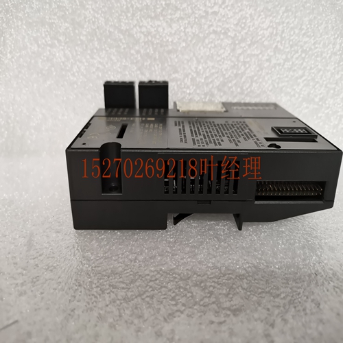
IS200ISBEH2ABB机器人卡件
则它还必须断言HMASTLOCK信号。该信号向任何从设备指示当前传输序列是不可分割的,因此必须在处理任何其他传输之前进行处理。通常,通过确保从机在微处理器SWP指令的读和写阶段之间不执行其他操作,锁定传输用于保持信号量的完整性。图3-7显示了带有微处理器SWP指令的HMASTLOCK信号。图3-7锁定传输注释锁定传输后,建议主设备插入IDLE传输。大多数从属设备不需要实现HMASTLOCK,因为它们只能按照接收的顺序执行传输。可以由多个主设备访问的从属设备,例如,多端口存储器控制器(MPMC)必须实现HMASTLOCK信号。允许主机在锁定传输序列的开始、中间或结束时为IDLE传输断言HMASTLOCK。允许在锁定传输序列的开始或结束时使用锁定的IDLE传输,但不建议这样做,因为这种行为会对系统的仲裁产生不利影响。也允许(但不建议)主设备为多个IDLE传输断言HMASTLOCK,然后在不执行非IDLE传输的情况下取消断言HMASTLOCK。这种行为会对系统的仲裁产生不利影响。要求锁定序列中的所有传输都指向同一从属地址区域。注:本规范的问题a中不存在确保锁定序列中的所有传输都指向同一从属地址区域的要求。必须验证旧组件,以确保其不会表现出这种行为。HADDR[31:0]A HCLK HWRITE读取(A)HRDATA[31:0]数据(A)HTRANS[1:0]NONSEQ NONSEQIDLE写入(A)A HWDATA[31:0]Data(A)HMASTLOCK 3传输3.4传输大小ARM IHI 0033B。b版权所有©2001、2006、2010、2015 ARM Limited或其附属公司。保留所有权利。3-33 ID102715非机密3.4传输大小HSIZE[2:0]表示数据传输的大小。表3-2列出了可能的传输大小。注:HSIZE设置的传输大小必须小于或等于数据总线的宽度。例如,对于32位数据总线,HSIZE只能使用值0b000、0b001或0b010。将HSIZE与HBURST结合使用,以确定包装突发的地址边界。HSIZE信号具有与地址总线完全相同的定时。然而,它们必须在整个突发传输过程中保持恒定。表3-2传输大小编码HSIZE[2]HSIZE[1]HSIZE[0]大小(位)描述0 0 0 8字节0 0 1 16半字0 1 0 32字0 1 1 64双字1 0 0 128 4字线1 0 1 256 8字线1 1 0 512-1 1 1 1024-3传输3.5突发操作3-34版权所有©2001、2006、2010、2015 ARM Limited或其附属公司。保留所有权利。ARM IHI 0033B.b非机密ID102715 3.5突发操作4、8和16拍突发、未定义长度突发和单次传输在本协议中定义。它支持递增和换行脉冲串:•递增脉冲串访问顺序位置,脉冲串中每个传输的地址是前一个地址的增量。•换行脉冲串在跨越地址边界时换行。地址边界被计算为突发中的拍数和传输大小的乘积。心跳数由HBURST控制,传输大小由HSIZE控制。例如,字(4字节)的四拍包装突发在16字节边界处访问包装。因此,如果脉冲串的起始地址是0x34,那么它包括四个到地址0x34、0x38、0x3C和0x30的传输。HBURST[2:0]控制突发类型。表3-3列出了可能的突发类型。主机不得尝试启动跨越1KB地址边界的递增突发。主机可以使用以下任一方式执行单次传输:•单次传输突发。•具有长度为1的突发的未定义长度突发。注:脉冲串大小表示脉冲串中的节拍数,而不是传输的字节数。如HSIZE[2:0]所示,通过将节拍数乘以每个节拍中的数据量,计算在一个脉冲串中传输的数据总量。突发中的所有传输必须与等于传输大小的地址边界对齐。例如,字传输必须与字地址边界对齐(HADDR[1:0]=0b00),半字传输必须对齐半字地址边界(HADDR[0]=0)。IDLE传输的地址也必须对齐,否则在模拟过程中,总线监视器可能会报告虚假警告。表3-3突发信号编码HBURST[2:0]类型描述0b000 SINGLE单传输突发0b001 INCR未定义长度的递增突发0b010 WRAP4 4位包裹突发0b011 INCR4 4位递增突发
locked accesses then it must also assert the HMASTLOCK signal. This signal indicates to any slave that the current transfer sequence is indivisible and must therefore be processed before any other transfers are processed. Typically the locked transfer is used to maintain the integrity of a semaphore, by ensuring that the slave does not perform other operations between the read and write phases of a microprocessor SWP instruction. Figure 3-7 shows the HMASTLOCK signal with a microprocessor SWP instruction. Figure 3-7 Locked transfer Note After a locked transfer, it is recommended that the master inserts an IDLE transfer. Most slaves have no requirement to implement HMASTLOCK because they are only capable of performing transfers in the order they are received. Slaves that can be accessed by more than one master, for example, a Multi-Port Memory Controller (MPMC) must implement the HMASTLOCK signal. It is permitted for a master to assert HMASTLOCK for IDLE transfers at the beginning, in the middle, or at the end of a sequence of locked transfers. Using locked IDLE transfers at the start or end of a locked transfer sequence is permitted, but not recommended, as this behavior can adversely affect the arbitration of the system. It is also permitted, but not recommended, for a master to assert HMASTLOCK for a number IDLE transfers and then deasserted HMASTLOCK without performing a non-IDLE transfer. This behavior can adversely affect the arbitration of the system. It is required that all transfers in a locked sequence are to the same slave address region. Note The requirement to ensure that all transfers in a locked sequence are to the same slave address region did not exist in Issue A of this specification. A legacy component must be verified to ensure that it does not exhibit this behavior. HADDR[31:0] A HCLK HWRITE Read (A) HRDATA[31:0] Data (A) HTRANS[1:0] NONSEQ NONSEQ IDLE Write (A) A HWDATA[31:0] Data (A) HMASTLOCK 3 Transfers 3.4 Transfer size ARM IHI 0033B.b Copyright © 2001, 2006, 2010, 2015 ARM Limited or its affiliates. All rights reserved. 3-33 ID102715 Non-Confidential 3.4 Transfer size HSIZE[2:0] indicates the size of a data transfer. Table 3-2 lists the possible transfer sizes. Note The transfer size set by HSIZE must be less than or equal to the width of the data bus. For example, with a 32-bit data bus, HSIZE must only use the values 0b000, 0b001, or 0b010. Use HSIZE in conjunction with HBURST, to determine the address boundary for wrapping bursts. The HSIZE signals have exactly the same timing as the address bus. However, they must remain constant throughout a burst transfer. Table 3-2 Transfer size encoding HSIZE[2] HSIZE[1] HSIZE[0] Size (bits) Description 0 0 0 8 Byte 0 0 1 16 Halfword 0 1 0 32 Word 0 1 1 64 Doubleword 1 0 0 128 4-word line 1 0 1 256 8-word line 1 1 0 512 - 1 1 1 1024 - 3 Transfers 3.5 Burst operation 3-34 Copyright © 2001, 2006, 2010, 2015 ARM Limited or its affiliates. All rights reserved. ARM IHI 0033B.b Non-Confidential ID102715 3.5 Burst operation Bursts of 4, 8, and 16-beats, undefined length bursts, and single transfers are defined in this protocol. It supports incrementing and wrapping bursts: • Incrementing bursts access sequential locations and the address of each transfer in the burst is an increment of the previous address. • Wrapping bursts wrap when they cross an address boundary. The address boundary is calculated as the product of the number of beats in a burst and the size of the transfer. The number of beats are controlled by HBURST and the transfer size is controlled by HSIZE. For example, a four-beat wrapping burst of word (4-byte) accesses wraps at 16-byte boundaries. Therefore, if the start address of the burst is 0x34, then it consists of four transfers to addresses 0x34, 0x38, 0x3C, and 0x30. HBURST[2:0] controls the burst type. Table 3-3 lists the possible burst types. Masters must not attempt to start an incrementing burst that crosses a 1KB address boundary. Masters can perform single transfers using either: • SINGLE transfer burst. • Undefined length burst that has a burst of length one. Note The burst size indicates the number of beats in the burst and not the number of bytes transferred. Calculate the total amount of data transferred in a burst by multiplying the number of beats by the amount of data in each beat, as indicated by HSIZE[2:0]. All transfers in a burst must be aligned to the address boundary equal to the size of the transfer. For example, word transfers must align to word address boundaries (HADDR[1:0] = 0b00), and halfword transfers to halfword address boundaries (HADDR[0] = 0). The address for IDLE transfers must also be aligned, otherwise during simulation it is likely that bus monitors could report spurious warnings. Table 3-3 Burst signal encoding HBURST[2:0] Type Description 0b000 SINGLE Single transfer burst 0b001 INCR Incrementing burst of undefined length 0b010 WRAP4 4-beat wrapping burst 0b011 INCR4 4-beat incrementing burst 0b100 WRAP8 8-beat wrapping burst 0b101 INCR8 8-beat incrementing burst 0b110 WRAP16 16-beat wrapping burst


