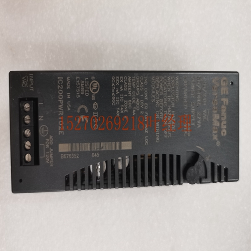
IS200IVFBG1A机械设备卡件
表2-4解码器信号名称目的地描述HSELxa从站每个从站都有自己的从站选择信号HSELx,该信号表示当前传输是针对所选从站的。当最初选择从设备时,它还必须监控HREADY的状态,以确保在响应当前传输之前,上一次总线传输已经完成。HSELx信号是地址总线的组合解码。参见第4-53页的地址解码。a、 HSELx中使用的字母x必须更改为系统中每个从属设备的唯一标识符。例如,HSEL_S1、HSEL_S2和HSEL_Memory。2信号说明2.5多路复用器信号ARM IHI 0033B。b版权所有©2001、2006、2010、2015 ARM Limited或其附属公司。保留所有权利。2-25 ID102715非保密2.5多路复用器信号表2-5列出了多路复用器生成的协议信号。表2-5多路复用器信号名称目的地描述HRDATA[31:0]主读数据总线,由解码器选择。HREADY主和从当为高电平时,HREADY信号向主和所有从指示上一次传输已完成。参见第4-54页的读取数据和响应多路复用器。解码器选择的HRESP主传输响应。解码器选择的HEXOKAY主独占响应。a.由于HRDATA[31:0]、HRESP和HEXOKAI信号通过多路复用器并保持相同的信号命名,因此这三个信号的完整信号描述见第2-23页表2-3。2信号描述2.5多路复用器信号2-26版权所有©2001、2006、2010、2015 ARM Limited或其附属公司。保留所有权利。ARM IHI 0033B.b非机密ID102715 ARM IHI 003 3B.b版权所有©2001、2006、2010、2015 ARM Limited或其附属公司。保留所有权利。3-27 ID102715非机密第3章传输本章描述了读写传输。它包含以下部分:•第3-28页的基本传输。•第3-30页上的传输类型。•第3-32页锁定传输。•转移尺寸见第3-33页。•第3-34页的突发操作。•第3-39页等待转账。•第3-44页的保护控制。•第3-45页的内存类型。3转让3.1基本转让3-28版权所有©2001、2006、2010、2015 ARM Limited或其附属公司。保留所有权利。ARM IHI 0033B.b非机密ID102715 3.1基本传输一个传输由两个阶段组成:地址持续一个HCLK周期,除非它被前一个总线传输扩展。数据可能需要几个HCLK周期。使用HREADY信号控制完成传输所需的时钟周期数。HWRITE控制与主机之间的数据传输方向。因此,当:•HWRITE为HIGH时,表示写入传输,并且主设备在写入数据总线上广播数据,HWDATA[31:0]•HWRITE为LOW时,执行读取传输,并且从设备必须在读取数据总线上生成数据,HRDATA[31:0。最简单的传输是没有等待状态的传输,因此传输由一个地址周期和一个数据周期组成。图3-1显示了一个简单的读传输,图3-2显示了一种简单的写传输。图3-1读取传输图3-2写入传输在没有等待状态的简单传输中:1。主机在HCLK的上升沿之后将地址和控制信号驱动到总线上。2.然后,从设备在HCLK的下一个上升沿上采样地址和控制信息。3.在从设备对地址和控制进行采样之后,它可以开始驱动适当的HREADYOUT响应。该响应由主机在HCLK的第三上升沿上采样。这个简单的示例演示了传输的地址和数据阶段如何在不同的时钟周期内发生。任何传输的地址阶段都发生在上一次传输的数据阶段。地址和数据的这种重叠对于总线的流水线性质来说是基本的,并且能够实现高性能操作,同时仍然为从设备提供足够的时间来提供对传输的响应。从设备可以在任何传输中插入等待状态,以增加完成时间。每个从机都有一个HREADYOUT信号,它在传输的数据阶段驱动该信号。互连负责组合来自所有从设备的HREADYOUT信号,以生成用于控制整体进度的单个HREADY信号。HADDR[31:0]A HCLK B地址阶段数据阶段HWRITE HRDATA[31:0]数据(A)HREADY HADDR[31:0]A HCLKB地址阶段信息阶段HWRITE HWDATA[31:0]数据(B)HREAD 3传输3.1基本传输ARM IHI 0033B。B版权所有©2001、2006、2010、2015 ARM Limited或其附属公司。保留所有权利。
Table 2-4 Decoder signals Name Destination Description HSELxa Slave Each slave has its own slave select signal HSELx and this signal indicates that the current transfer is intended for the selected slave. When the slave is initially selected, it must also monitor the status of HREADY to ensure that the previous bus transfer has completed, before it responds to the current transfer. The HSELx signal is a combinatorial decode of the address bus. See Address decoding on page 4-53. a. The letter x used in HSELx must be changed to a unique identifier for each slave in a system. For example, HSEL_S1, HSEL_S2, and HSEL_Memory. 2 Signal Descriptions 2.5 Multiplexor signals ARM IHI 0033B.b Copyright © 2001, 2006, 2010, 2015 ARM Limited or its affiliates. All rights reserved. 2-25 ID102715 Non-Confidential 2.5 Multiplexor signals Table 2-5 lists the protocol signals generated by the multiplexor. Table 2-5 Multiplexor signals Name Destination Description HRDATA[31:0] Master Read data bus, selected by the decoder.a HREADY Master and slave When HIGH, the HREADY signal indicates to the master and all slaves, that the previous transfer is complete. See Read data and response multiplexor on page 4-54. HRESP Master Transfer response, selected by the decoder.a HEXOKAY Master Exclusive okay, selected by the decoder.a a. Because the HRDATA[31:0], HRESP, and HEXOKAY signals pass through the multiplexor and retain the same signal naming, the full signal descriptions for these three signals are provided in Table 2-3 on page 2-23. 2 Signal Descriptions 2.5 Multiplexor signals 2-26 Copyright © 2001, 2006, 2010, 2015 ARM Limited or its affiliates. All rights reserved. ARM IHI 0033B.b Non-Confidential ID102715 ARM IHI 0033B.b Copyright © 2001, 2006, 2010, 2015 ARM Limited or its affiliates. All rights reserved. 3-27 ID102715 Non-Confidential Chapter 3 Transfers This chapter describes read and write transfers. It contains the following sections: • Basic transfers on page 3-28. • Transfer types on page 3-30. • Locked transfers on page 3-32. • Transfer size on page 3-33. • Burst operation on page 3-34. • Waited transfers on page 3-39. • Protection control on page 3-44. • Memory types on page 3-45. 3 Transfers 3.1 Basic transfers 3-28 Copyright © 2001, 2006, 2010, 2015 ARM Limited or its affiliates. All rights reserved. ARM IHI 0033B.b Non-Confidential ID102715 3.1 Basic transfers A transfer consists of two phases: Address Lasts for a single HCLK cycle unless its extended by the previous bus transfer. Data Might require several HCLK cycles. Use the HREADY signal to control the number of clock cycles required to complete the transfer. HWRITE controls the direction of data transfer to or from the master. Therefore, when: • HWRITE is HIGH, it indicates a write transfer and the master broadcasts data on the write data bus, HWDATA[31:0] • HWRITE is LOW, a read transfer is performed and the slave must generate the data on the read data bus, HRDATA[31:0]. The simplest transfer is one with no wait states, so the transfer consists of one address cycle and one data cycle. Figure 3-1 shows a simple read transfer and Figure 3-2 shows a simple write transfer. Figure 3-1 Read transfer Figure 3-2 Write transfer In a simple transfer with no wait states: 1. The master drives the address and control signals onto the bus after the rising edge of HCLK. 2. The slave then samples the address and control information on the next rising edge of HCLK. 3. After the slave has sampled the address and control it can start to drive the appropriate HREADYOUT response. This response is sampled by the master on the third rising edge of HCLK. This simple example demonstrates how the address and data phases of the transfer occur during different clock cycles. The address phase of any transfer occurs during the data phase of the previous transfer. This overlapping of address and data is fundamental to the pipelined nature of the bus and enables high performance operation while still providing adequate time for a slave to provide the response to a transfer. A slave can insert wait states into any transfer to enable additional time for completion. Each slave has an HREADYOUT signal that it drives during the data phase of a transfer. The interconnect is responsible for combining the HREADYOUT signals from all slaves to generate a single HREADY signal that is used to control the overall progress. HADDR[31:0] A HCLK B Address phase Data phase HWRITE HRDATA[31:0] Data (A) HREADY HADDR[31:0] A HCLK B Address phase Data phase HWRITE HWDATA[31:0] Data (A) HREADY 3 Transfers 3.1 Basic transfers ARM IHI 0033B.b Copyright © 2001, 2006, 2010, 2015 ARM Limited or its affiliates. All rights reserved.


