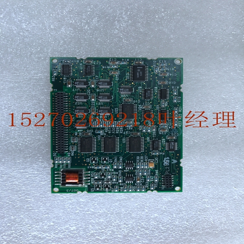
IS200JGNDG1A工业自动化卡件
AMBA AHB实现了高性能、高时钟频率系统所需的功能,包括:•突发传输。•单时钟边沿操作。•非三态实施。•宽数据总线配置,64、128、256、512和1024位。最常见的AHB从设备是内部存储器设备、外部存储器接口和高带宽外围设备。尽管低带宽外设可以作为AHB从设备,但出于系统性能原因,它们通常位于AMBA高级外设总线(APB)上。更高性能的AHB和APB之间的桥接使用AHB从设备(称为APB桥)完成。图1-1显示了具有AHB主设备和三个AHB从设备的单主AHB系统设计。总线互连逻辑由一个地址解码器和从-主多路复用器组成。解码器监控来自主设备的地址,以便选择合适的从设备,多路复用器将相应的从设备输出数据路由回主设备。AHB还通过使用互连组件支持多主机设计,该互连组件提供从不同主机到适当从机的仲裁和路由信号。图1-1 AHB框图注:图1-1仅显示了主地址和数据总线以及典型的数据路由。并非所有信号都显示。AHB系统的主要部件类型如:•第1-15页的主部件。•第1-15页的从属设备。•第1-16页互连。主从1从2从3解码器HRDATA[31:0]HRDATA_3 HRDATA_1 HRDATA_2多路复用器选择HWDATA[31:0]HADDR[31:0]HSEL_1 HSEL_2 HSEL_3 1简介1.1关于协议ARM IHI 0033B。b版权所有©2001、2006、2010、2015 ARM Limited或其附属公司。保留所有权利。1-15 ID102715非机密1.1.1主机A主机提供地址和控制信息以启动读写操作。图1-2显示了主界面。注:图1-2中的图表不包括AHB5中定义的附加信号。图1-2主界面1.1.2从设备从设备响应系统中主设备发起的传输。从设备使用来自解码器的HSELx选择信号来控制何时响应总线传输。从设备向主设备发送信号:•总线传输的完成或扩展。•总线传输的成功或失败。图1-3显示了从属接口。注:图1-3中的图表不包括AHB5中定义的其他信号。图1-3从属接口主HREADY HRESETn HCLK HRESP HRDATA[31:0]HTRANS[1:0]HADDR[31:0]HSIZE[2:0]HBURST[2:0]HPROT[3:0]HWDATA[31:0]HWRITE HMASTLOCK数据传输响应全局信号地址和控制数据从属HSELx HREADY HADDR[31:0]HWRITE HTRANS[1:0]HSIZE[2:0]HRURST[2:0.]HPROT[3:0]HMASTLOCK HRESETnHCLK HWDATA[31:0]HREADYOUT HRDATA[31]:0]传输响应全局信号数据地址和控制数据选择HRESP 1简介1.1关于协议1-16版权所有©2001、2006、2010、2015 ARM Limited或其附属公司。保留所有权利。ARM IHI 0033B.b非机密ID102715 1.1.3互连互连组件提供系统中主设备和从设备之间的连接。单个主系统只需要使用解码器和多路复用器,如以下章节所述。多主系统需要使用互连,该互连提供仲裁和从不同主设备到适当从设备的信号路由。地址、控制和写入数据信令需要此路由。本说明书中未提供用于多主系统(例如单层或多层互连)的不同方法的进一步细节。有关实现多层AHB Lite互连的更多信息,请参阅多层AHB技术概述(ARM DVI 0045)。解码器该组件对每次传输的地址进行解码,并为参与传输的从设备提供选择信号。它还向多路复用器提供控制信号。在使用两个或多个从设备的所有实现中,都需要单个集中式解码器。有关详细信息,请参阅第4-53页的地址解码。多路复用器从设备到主设备的多路复用器需要将读数据总线和从设备到主机的响应信号多路复用。解码器为多路复用器提供控制。在使用两个或多个从设备的所有实现中,都需要一个集中式多路复用器。有关详细信息,请参阅第4-54页的读取数据和响应多路复用器。1简介1.2 AHB修订版ARM IHI 0033B。b版权所有
AMBA AHB implements the features required for high-performance, high clock frequency systems including: • Burst transfers. • Single clock-edge operation. • Non-tristate implementation. • Wide data bus configurations, 64, 128, 256, 512, and 1024 bits. The most common AHB slaves are internal memory devices, external memory interfaces, and high-bandwidth peripherals. Although low-bandwidth peripherals can be included as AHB slaves, for system performance reasons, they typically reside on the AMBA Advanced Peripheral Bus (APB). Bridging between the higher performance AHB and APB is done using an AHB slave, known as an APB bridge. Figure 1-1 shows a single master AHB system design with the AHB master and three AHB slaves. The bus interconnect logic consists of one address decoder and a slave-to-master multiplexor. The decoder monitors the address from the master so that the appropriate slave is selected and the multiplexor routes the corresponding slave output data back to the master. AHB also supports multi-master designs by the use of an interconnect component that provides arbitration and routing signals from different masters to the appropriate slaves. Figure 1-1 AHB block diagram Note Figure 1-1 shows only the main address and data buses and typical data routing. Not all signals are shown. The main component types of an AHB system are described in: • Master on page 1-15. • Slave on page 1-15. • Interconnect on page 1-16. Master Slave 1 Slave 2 Slave 3 Decoder HRDATA[31:0] HRDATA_3 HRDATA_1 HRDATA_2 Multiplexor select HWDATA[31:0] HADDR[31:0] HSEL_1 HSEL_2 HSEL_3 1 Introduction 1.1 About the protocol ARM IHI 0033B.b Copyright © 2001, 2006, 2010, 2015 ARM Limited or its affiliates. All rights reserved. 1-15 ID102715 Non-Confidential 1.1.1 Master A master provides address and control information to initiate read and write operations. Figure 1-2 shows a master interface. Note The diagram in Figure 1-2 does not include the additional signals defined in AHB5. Figure 1-2 Master interface 1.1.2 Slave A slave responds to transfers initiated by masters in the system. The slave uses the HSELx select signal from the decoder to control when it responds to a bus transfer. The slave signals back to the master: • The completion or extension of the bus transfer. • The success or failure of the bus transfer. Figure 1-3 shows a slave interface. Note The diagram in Figure 1-3 does not include the additional signals defined in AHB5. Figure 1-3 Slave interface Master HREADY HRESETn HCLK HRESP HRDATA[31:0] HTRANS[1:0] HADDR[31:0] HSIZE[2:0] HBURST[2:0] HPROT[3:0] HWDATA[31:0] HWRITE HMASTLOCK Data Transfer response Global signals Address and control Data Slave HSELx HREADY HADDR[31:0] HWRITE HTRANS[1:0] HSIZE[2:0] HBURST[2:0] HPROT[3:0] HMASTLOCK HRESETn HCLK HWDATA[31:0] HREADYOUT HRDATA[31:0] Transfer response Global signals Data Address and control Data Select HRESP 1 Introduction 1.1 About the protocol 1-16 Copyright © 2001, 2006, 2010, 2015 ARM Limited or its affiliates. All rights reserved. ARM IHI 0033B.b Non-Confidential ID102715 1.1.3 Interconnect An interconnect component provides the connection between masters and slaves in a system. A single master system only requires the use of a Decoder and Multiplexor, as described in the following sections. A multi-master system requires the use of an interconnect that provides arbitration and the routing of signals from different masters to the appropriate slaves. This routing is required for address, control, and write data signaling. Further details of the different approaches used for multi-master systems, such as single layer or multi-layer interconnects, are not provided within this specification. See Multi-layer AHB Technical Overview (ARM DVI 0045) for more information about implementing a multi-layer AHB-Lite interconnect. Decoder This component decodes the address of each transfer and provides a select signal for the slave that is involved in the transfer. It also provides a control signal to the multiplexor. A single centralized decoder is required in all implementations that use two or more slaves. See Address decoding on page 4-53 for more information. Multiplexor A slave-to-master multiplexor is required to multiplex the read data bus and response signals from the slaves to the master. The decoder provides control for the multiplexor. A single centralized multiplexor is required in all implementations that use two or more slaves. See Read data and response multiplexor on page 4-54 for more information. 1 Introduction 1.2 AHB revisions ARM IHI 0033B.b Copyrigh


