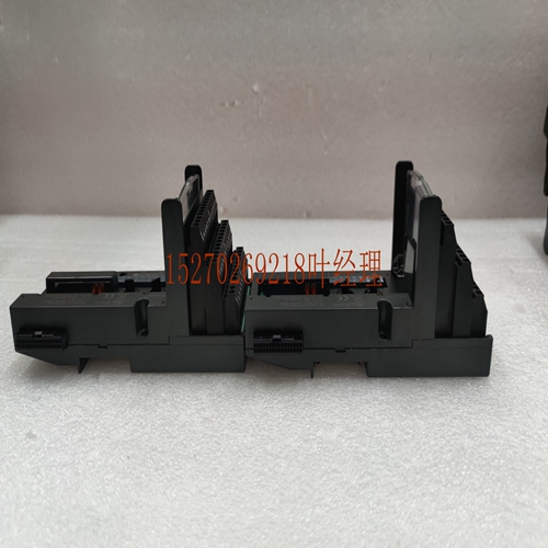
IS200JPDLG1A工控模块系统备件
载波1线点无辅助端子2线点公共1辅助端子†3辅助端子2辅助端子*3辅助端子3线点公共+V 2辅助端子†6辅助端子4辅助端子*6辅助端子4线点公共+V-V 3辅助端子†9辅助端子6辅助端子*9辅助端子†对于仅使用一排端子进行点接线的16点模块,可使用短路棒提供额外端子。请参阅“使用短路棒”一节。2-36 VersaMax模块、电源和托架用户手册GFK-1504N 2例如,16点模块可能使用3个辅助端子用于4线设备,如下图所示。I类区域2 Ex nA IIC T4 OC Ta Ex nV II T4 Demko N点连接公共连接+V连接-V连接辅助端子可容纳高达8 a的电流水平和高达264 V AC的电压。高达300 V AC的电压瞬变不会造成损坏。安装辅助端子通过将接线片插入托架或插入端子上的插槽并向下按压来安装辅助端子。如果需要,可以通过面板安装孔插入螺钉以增加稳定性。在连接现场接线之前,辅助载体必须安装在载体或插入端子上。辅助端子的导线规格导线规格取决于端子类型。对于箱式或弹簧型端子,每个端子容纳一根实心或绞合AWG#14(平均横截面2.1mm2)至AWG#22(平均横截面积0.36mm2)导线,或两根AWG#18(平均横面积0.86mm2)导线。对于屏障型端子,每个端子容纳一条或两条从AWG#22(平均横截面0.36mm2)到AWG#14(平均横截面积2.1mm2)的实心或绞合导线。使用额定温度为90摄氏度的铜线。在同一位置插入两根电线时,电线的尺寸和类型必须相同(实心或绞合)。GFK-1504N第2章安装2-37 2使用短接杆短接杆(零件号IC200ACC303,数量2)是为仅包含一个板的模块提供额外总线端子的经济高效的解决方案。短路棒的最大载流能力为每点2安培。请参阅各个模块的说明,以确定短路棒是否可用于特定模块。下图说明了在2行或3行载体上使用短路棒为模块提供额外的现场接线连接。带有两排端子的托架连接示例安装模块前,必须将短路杆直接安装在托架上。A B B A A B 2-38 VersaMax模块、电源和托架用户手册GFK-1504N 2在安装了短路棒的情况下,托架或插入式端子装置上未使用的端子可以与前面所述的辅助端子相同的方式使用。现场设备图16点模块32点模块盒、弹簧或连接器托架阻挡式托架盒、弹簧、或连接器托架,带有短路杆阻挡式托架和短路杆盒、弹簧,或连接器载体屏障式载体1线点无辅助端子2线点公共1辅助端子3辅助端子无辅助端子载体上屏障端子右侧2辅助端子3附加端子3线点公共+V 2辅助端子6辅助
Carrier 1-wire Point no Auxiliary Terminals 2-wire Point Common 1 Auxiliary Terminals † 3 Auxiliary Terminals 2 Auxiliary Terminals * 3 Auxiliary Terminals 3-wire Point Common +V 2 Auxiliary Terminals † 6 Auxiliary Terminals 4 Auxiliary Terminals * 6 Auxiliary Terminals 4-wire Point Common +V -V 3 Auxiliary Terminals † 9 Auxiliary Terminals 6 Auxiliary Terminals * 9 Auxiliary Terminals † For 16-point modules that only use one row of terminals for point wiring, a shorting bar may be used to provide extra terminals. Refer to the section , Using A Shorting Bar. 2-36 VersaMax Modules, Power Supplies and CarriersUser Manual GFK-1504N 2 For example, a 16-point module might use 3 Auxiliary Terminals for 4-wire devices as displayed in the following figure. CLASS I ZONE 2 Ex nA IIC T4 OC Ta Ex nV II T4 Demko N Point Connections Common Connections +V Connections -V Connections Auxiliary Terminals accommodate current levels up to 8 A and voltage up to 264 V AC. Voltage transients up to 300 V AC will not cause damage. Installing Auxiliary Terminals Auxiliary Terminals are installed by inserting the tabs into the slots on the Carrier or Interposing Terminals and pressing downward. Screws can be inserted through the panel-mount holes for added stability if needed. Auxiliary Carriers must be installed on the Carrier or Interposing Terminals before connecting field wiring. Wire Specifications for Auxiliary Terminals Wire specifications depend on the terminal type. For box-type or spring type terminals, each terminal accommodates one solid or stranded AWG #14 (avg. 2.1mm2 cross section) to AWG #22 (avg. 0.36mm2 cross section) wire, or two wires up to AWG #18 (avg. 0.86mm2 cross section). For barrier-type terminals, each terminal accommodates one or two solid or stranded wires from AWG #22 (avg. 0.36mm2 cross section) to AWG #14 (avg. 2.1mm2 cross section). Use copper wire rated for 90 deg C. When inserting two wires in the same position, the wires must be the same size and type (solid or stranded). GFK-1504N Chapter 2 Installation 2-37 2 Using Shorting Bars Shorting Bars (part number IC200ACC303, quantity 2) can be a cost-effective solution for providing additional bussed terminals for modules that include only one board. The shorting bar has a maximum current-carrying capacity of 2 Amps per point. Refer to the individual module descriptions to determine whether a shorting bar can be used for a particular module. The following figures illustrate the use of a Shorting Bar on a 2-row or 3-row carrier to provide extra field wiring connections for an module. Example Connection for Carriers with Two Rows of Terminals A Shorting Bar must be installed directly on the carrier before installing the module. A B B A A B 2-38 VersaMax Modules, Power Supplies and CarriersUser Manual GFK-1504N 2 With a Shorting Bar in place, the unused terminals on the Carrier or Interposing Terminals unit can be used in the same way as the Auxiliary Terminals described earlier. Field Device Diagram 16 Point Module 32 Point Module Box-, Spring-, or Connector Carrier BarrierStyle Carrier Box-, Spring-, or Connector Carrier with a Shorting Bar Barrier-Style Carrier with a Shorting Bar Box-, Spring-, or Connector Carrier Barrier-Style Carrier 1-wire Point no Auxiliary Terminals 2-wire Point Common 1 Auxiliary Terminals 3 Auxiliary Terminals no Auxiliary Terminals Right side of barrier terminals on Carrier 2 Auxiliary Terminals 3 Auxiliary Terminals 3-wire Point Common +V 2 Auxiliary Terminals 6 Auxiliary


