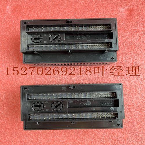
IS200PMCIHAAA6BA00工业卡件,DCS卡件
2.将DIN导轨上的模块滑离主机架中的CPU或NIU。3.使用小螺丝刀,拉下模块底部的卡舌,将模块从DIN导轨上提起。2-8 VersaMax模块、电源和托架用户手册GFK-1504N 2安装扩展接收器模块扩展接收器模块(IC200ERM001或002)必须安装在每个VersaMax扩展机架的最左侧插槽中。1.将标签插入模块左上角的小检修门内。2.将模块连接到扩展机架左端的DIN导轨。3.使用模块左上角检修门下的旋转开关选择扩展机架ID(1至7)。每个机架必须设置为不同的机架ID。对于单端电缆(仅限一个扩展机架),请将机架ID设置为1。5 7 6 4 1 3 2 0 4. 在扩展接收器顶部安装VersaMax电源模块。请参阅“安装电源”一节。5.连接电缆。如果系统包含扩展发射器模块,请将终端插头连接到最后一个扩展接收器模块上的EXP2端口。6.完成系统安装后,接通电源并观察模块LED。PWR EXP RX SCAN On(压水堆EXP RX扫描打开)指示存在5VDC电源。关闭表示无5VDC电源。闪烁或打开表示模块正在扩展总线上通信关闭表示模块未通信绿色表示CPU/NIU正在扩展机架中扫描。琥珀色表示未扫描。GFK-1504N第2章安装2-9 2拆卸扩展接收器模块1。确保机架电源已关闭。从扩展接收器模块上卸下电源模块。3.将DIN导轨上的扩展接收器模块滑离其他模块。4.使用小螺丝刀,向下拉动模块底部的卡舌,将模块从DIN导轨上提起。2-10 VersaMax模块、电源和托架用户手册GFK-1504N 2连接扩展电缆:RS-485差分对于多机架扩展系统,将电缆从扩展发射机上的扩展端口连接到扩展接收机,如下图所示。如果所有扩展接收机均为隔离型(IC200ERM001),最大总电缆长度为750米。如果扩展总线包括任何非隔离扩展接收器(IC200ERM002),则最大总电缆长度为15米。PS CPU/NIU PS ERM PS ERM ETM VersaMax ExpansionRack 1端接插头15M,带任何IC200ERM002 ERM 750M,带所有IC200ERR001 ERM VersaMax PLC或站主机架(0)IC200CBL601,VersaMax expansionRack7 602、615将端接插头(随扩展发射机模块提供)安装到最后一个扩展接收机的下部端口。备件端接插头可单独购买,零件号为IC200ACC201(数量2)。RS-485差分机架间连接(IC200CBL601、602、615)扩展发射机或扩展接收机模块发送端口PIN 2 3 5 6 8 9 12 13 16 17 20 21 24 25 7 23 1 FRAME+FRAMERIRQ/+RIRQ/-RUN+RUNRERR+RERRIODT+IODTRSEL+RSELIOCLK+IOCLK 0V SHIELD PIN 2 3 6 8 9 13 16 17 21 24 25 23 1 FRAM+FRAMERARQ/+RI RQ/-RUN+RUNRER+RERRIO DT+IODRSEL+RSELIOC LK+IOCLK0V 0V屏蔽26针内螺纹26针外螺纹26针公螺纹26针内可变(见文本)扩展接收器模块接收端口构建定制扩展电缆定制扩展电缆可使用连接器套件IC200ACC202、压接器AMP 90800-1和Belden 8138、Manhattan/CDT M2483、Alpha 3498C或等效AWG#28(0.089mm2)电缆构建。GFK-1504N第2章安装2-11 2连接扩展电缆:单端用于双机架本地
2. Slide module on DIN rail away from the CPU or NIU in the main rack. 3. Using a small screwdriver, pull down on the tab on the bottom of the module and lift the module off the DIN rail. 2-8 VersaMax Modules, Power Supplies and CarriersUser Manual GFK-1504N 2 Installing an Expansion Receiver Module An Expansion Receiver Module (IC200ERM001 or 002) must be installed in the leftmost slot of each VersaMax expansion rack. 1. Insert the label inside the small access door at the upper left corner of the module. 2. Attach the module to the DIN rail at the left end of the expansion rack. 3. Select the expansion rack ID (1 to 7) using the rotary switch under the access door at upper left corner of the module. Each rack must be set to a different rack ID. With a single-ended cable (one expansion rack only), set the Rack ID to 1. 5 7 6 4 1 3 2 0 4. Install a VersaMax Power Supply module on top of the Expansion Receiver. Refer to the section, Installing a Power Supply. 5. Attach the cables. If the system includes an Expansion Transmitter Module, attach the terminator plug to the EXP2 port on the last Expansion Receiver Module. 6. After completing system installation, apply power and observe the module LEDs. PWR EXP RX SCAN On indicates presence of 5VDC power. Off indicates no 5VDC power. Blinking or On indicates module is communicating on expansion bus Off indicates module not communicating Green indicates CPU/NIU is scanning in expansion racks. Amber indicates not scanning. GFK-1504N Chapter 2 Installation 2-9 2 Removing an Expansion Receiver Module 1. Make sure rack power is off. 2. Un-install the Power Supply module from the Expansion Receiver Module. 3. Slide the Expansion Receiver Module on DIN rail away from the other modules. 4. Using a small screwdriver, pull down on the tab on the bottom of the module and lift the module off the DIN rail. 2-10 VersaMax Modules, Power Supplies and CarriersUser Manual GFK-1504N 2 Connecting the Expansion Cable: RS-485 Differential For a multiple-rack expansion system, connect the cable from the expansion port on the Expansion Transmitter to the Expansion Receivers as displayed in the following figure. If all the Expansion Receivers are the Isolated type (IC200ERM001), the maximum overall cable length is 750 meters. If the expansion bus includes any non-isolated Expansion Receivers (IC200ERM002), the maximum overall cable length is 15 meters. PS CPU/NIU PS ERM PS ERM ETM VersaMax ExpansionRack 1 Terminator Plug 15M with any IC200ERM002 ERMs 750M with all IC200ERM001 ERMs VersaMax PLC or Station Main Rack (0) IC200CBL601, VersaMax ExpansionRack 7 602, 615 Install the Terminator Plug (supplied with the Expansion Transmitter module) into the lower port on the last Expansion Receiver. Spare Terminator Plugs can be purchased separately as part number IC200ACC201 (Qty 2). RS-485 Differential Inter-Rack Connection (IC200CBL601, 602, 615) Expansion Transmitter or Expansion Receiver Module Transmitting Port PIN 2 3 5 6 8 9 12 13 16 17 20 21 24 25 7 23 1 FRAME+ FRAMERIRQ/+ RIRQ/- RUN+ RUNRERR+ RERRIODT+ IODTRSEL+ RSELIOCLK+ IOCLK0V 0V SHIELD PIN 2 3 5 6 8 9 12 13 16 17 20 21 24 25 7 23 1 FRAME+ FRAMERIRQ/+ RIRQ/- RUN+ RUNRERR+ RERRIODT+ IODTRSEL+ RSELIOCLK+ IOCLK0V 0V SHIELD 26-PIN FEMALE 26-PIN MALE 26-PIN MALE 26-PIN FEMALE VARIABLE (SEE TEXT) Expansion Receiver Module Receiving Port Building a Custom Expansion Cable Custom expansion cables can be built using Connector Kit IC200ACC202, Crimper AMP 90800-1, and Belden 8138, Manhattan/CDT M2483, Alpha 3498C, or equivalent AWG #28 (0.089mm2 ) cable. GFK-1504N Chapter 2 Installation 2-11 2 Connecting the Expansion Cable: Single-ended For a two-rack local


