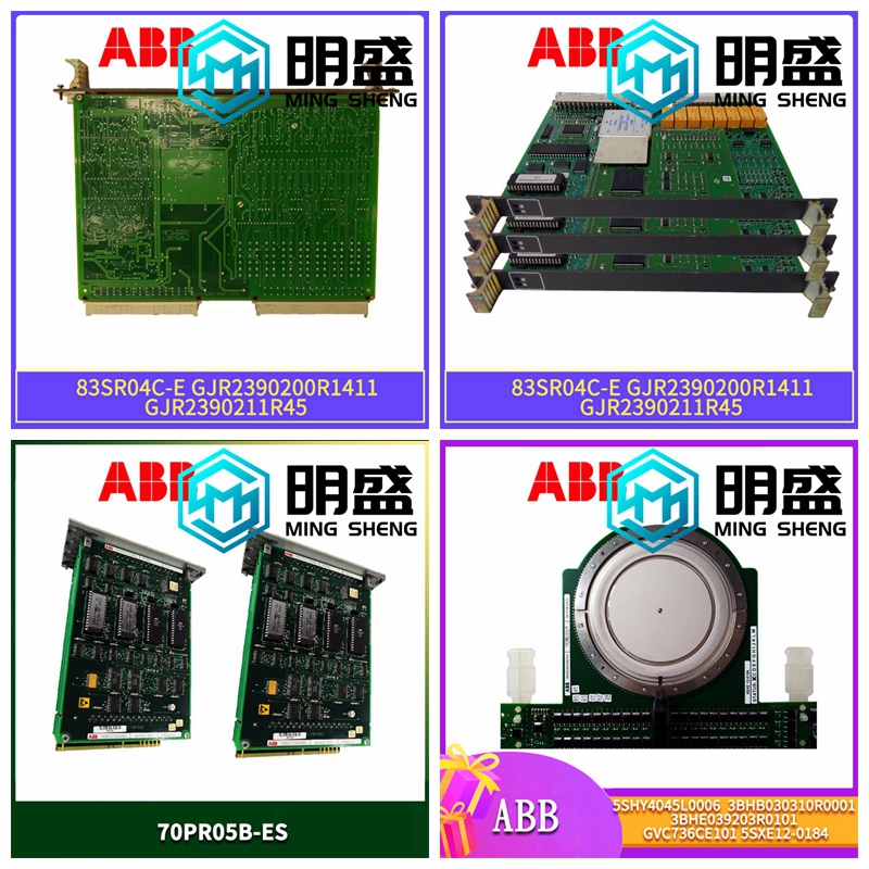
IS200STAIH1ABB处理器卡件
GMR配置实用程序限制对内存安全关键区域的访问。可以写入的区域按类型、地址起始位置和长度大小进行分隔。这大大降低了来自外部设备的“WRITE”命令被放置在内存关键区域的可能性。类型描述是否可以启用写访问?%R系统寄存器。存储程序数据(如计算结果)的16位字引用。是%AI模拟输入寄存器。16位模拟输入寄存器保存一个模拟输入或其他值的值。是%AQ模拟输出寄存器。16位模拟输出寄存器保存一个模拟输出或其他值的值。是%P程序寄存器。16位字参考,用于存储_MAIN块中的程序数据。可以从所有程序块访问该数据。没有%L本地寄存器。16位字引用,用于存储块特有的程序数据。无%I输入参考。位参考位于输入状态表中,该表存储上次输入扫描期间从输入模块接收的所有输入的状态。使用配置软件将参考地址分配给离散输入模块。是%Q物理输出参考。位引用位于输出状态表中,该表存储应用程序最后设置的输出引用的状态。该输出状态表的值在程序扫描结束时发送到输出模块。使用配置软件为离散输出模块分配参考地址。Logicmaster 90–70软件的线圈检查功能检查继电器线圈或功能输出的%Q参考的多次使用。是%M内部引用。一种可以保留或不保留的位引用。Logicmaster 90–70软件的线圈检查功能检查%M参考与继电器线圈或功能输出的多次使用。是%T临时引用。这些位参考从未针对多个线圈使用进行检查,因此即使启用了线圈使用检查,也可以在同一程序中多次使用。%T可用于在使用剪切/粘贴和文件写入/包含功能时防止线圈使用冲突。由于此内存是临时使用的,因此它不会通过断电或RUN–TO–STOP–TO–RUN转换而保留,也不会与保留线圈一起使用。yes%S–%SC系统状态参考。%S、%SA、%SB和%SC位参考用于访问特殊PLC数据,如计时器、扫描信息和故障信息。例如,%SC0012位可用于检查PLC故障表的状态。无%G–%GE全球数据参考。这些位参考用于访问几个PLC之间共享的数据。它们可以用于触点和保持线圈,因为记忆总是保持的。%G-%GE不能用于非保持线圈。%G全局数据存储器%GD%GE是%GA全局数据存储器/GB%GC编号GFT-177A 6-1 6节通信T M R G M RTM本节旨在概述可并入Genius模块化冗余系统的应用程序通信能力。这里总结了各个通信模块,并在第4节中进行了更详细的描述。GMR与分布式控制系统和HMI系统安全系统(如GMR)通常连接到过程控制器或分布式控制系统。GMR系统通常是独立的,并与分布式控制系统隔离,以确保其安全功能免受过程控制器故障的影响。GMR有一个内置的“有限内存写入”功能,确保只有外部接口专门访问的内存区域才能写入数据。
The GMR configuration utility restricts access to safety critical areas of the memory. Areas that can be written to are segregated by type, address starting location, and size in length. This greatly reduces the possibility that a ‘WRITE’ command from an external device will be placed in a critical area of memory. Type Description Can Write Access be Enabled? %R System registers. 16–bit word references that store program data such as the results of calculations. yes %AI Analog input registers. A 16–bit analog input register holds the value of one analog input or other value. yes %AQ Analog output registers. A 16–bit analog output register holds the value of one analog output or other value. yes %P Program registers. 16–bit word references which store program data from the _MAIN block. This data can be accessed from all program blocks. no %L Local registers. 16–bit word references which store program data unique to a block. no %I Input references. Bit references located in the input status table, which stores the state of all inputs received from input modules during the last input scan. A reference address is assigned to discrete input modules using the configuration software. yes %Q Physical output references. Bit references located in the output status table, which stores the state of the output references as last set by the application program. This output status table’s values are sent to output modules at the end of the program scan. A reference address is assigned to discrete output modules using the configuration software. The coil check function of Logicmaster 90–70 software checks for multiple uses of %Q references with relay coils or outputs on functions. yes %M Internal references. A bit reference that may be either retentive or non–retentive. The coil check function of Logicmaster 90–70 software checks for multiple uses of %M references with relay coils or outputs on functions. yes %T Temporary references. These bit references are never checked for multiple coil use, so they can be used many times in the same program even when coil use checking is enabled. %T may be used to prevent coil use conflicts while using the cut/paste and file write/include functions. Because this memory is intended for temporary use, it is never retained through power loss or RUN–TO–STOP– TO–RUN transitions and is not used with retentive coils. yes %S – %SC System status references. The %S, %SA, %SB, and %SC bit references are used to access special PLC data such as timers, scan information, and fault information. For example, the %SC0012 bit can be used to check the status of the PLC fault table. no %G – %GE Global data references. These bit references are used to access data shared among several PLCs. They can be used on contacts and retentive coils because the memory is always retentive. %G - %GE cannot be used on non–retentive coils. %G Global Data memory %GD %GE yes %GA Global Data memory %GB %GC no GFT-177A 6-1 6 Section Communications T M R G M RTM The purpose of this section is to provide an overview of application communications capabilities that can be incorporated into a Genius Modular Redundancy system. Individual communications modules are summarized here, and described in more detail in Section 4. GMR with Distributed Control Systems and HMI Systems Safety systems such as GMR generally interface to a process controller or Distributed Control System. The GMR system is usually independent and isolated from the Distributed Control System to ensure that its safety functions are protected from failures of the process controller. GMR has a built-in Limited Memory Write feature which ensures that only those areas of memory specifically made accessible to external interfaces can have data written to it.


