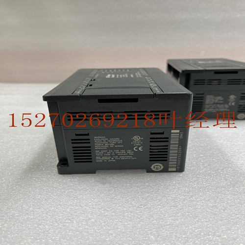
IS200TPROH1C处理器卡件
可以使用符合相同规格的任何零件。I/O电缆数据表C GFK-0898F附录C–I/O电缆数据图C-5扩展端口引脚分配下表列出了构建远程电缆时需要的扩展端口引脚。电缆之间的所有连接都是点对点的,即一端的针脚2到另一端的针脚3,针脚3到针脚3,等等。表B-1。扩展端口引脚分配引脚号信号功能16 DIODT I/O串行数据正极17 DIODT/I/O串行数据负极24 DIOCLK I/O串行时钟正极25 DIOCLK/I/O串行时钟负极20 DRSEL远程选择正极21 DRSEL/远程选择负极12 DRPERR奇偶校验错误正极13 DRPERR/奇偶校验错误负极8 DRMRUN远程运行正极9 DRMRUN/远程运行负极2 DFRAME循环帧正极3 DFRAME/循环帧负极1 FGND帧接地用于电缆屏蔽7 0V逻辑接地I/O扩展总线端子当两个或多个底板在扩展系统中连接在一起时,I/O扩展总线必须正确端接。I/O总线必须在扩展系统中的最后一个基板上终止。每个sigl在适当的引脚之间用120欧姆、1/4瓦的电阻器d端接,如下所示(也见上表):引脚16-17;24 - 25; 20 - 21; 12 - 13; 8 - 9; 2-3 I/O总线终端可通过以下方式之一完成:在系统的最后一个扩展基板(本地扩展基板或远程基板)上安装I/O总线终端插头(目录号IC693ACC307)。终端插头有一个电阻器组,物理安装在连接器内部。I/O总线端子插头随每个基板一起装运;只有扩展链中的最后一个基板才能安装I/O总线端子插头。未使用的I/O总线端子插头可以丢弃或保存为备件。如果扩展系统只有一个扩展底板,则可以通过安装50英尺(15米)I/O扩展电缆(目录号IC693CBL302或IC693CBL 314)作为最后一根电缆来终止I/O总线。这些电缆的终端电阻器安装在连接到扩展底板连接器的一端。您还可以构建一条定制电缆,将终端电阻器d连接到适当的引脚,以便安装在总线末端。C C-6 Series 90-30 PLC I/O模块规格–2000 GFK-0898F屏蔽处理所有GE Fanuc工厂电缆均采用连续或100%屏蔽。这意味着编织电缆屏蔽层围绕连接器的整个周边连接到连接器的金属外壳。这为耦合到电缆屏蔽上的任何ise能量提供了到框架接地的低阻抗路径。对于图10-18所示的定制长度电缆,当使用与电缆编织和箔屏蔽以及端子端连接器外壳接触的金属化连接器盖时,可获得最佳的抗干扰性。仅将漏极焊接到连接器外壳是不够的。
Any part meeting the same specification can be used. I/O Cable Data Sheets C GFK-0898F Appendix C – I/O Cable Data Sheets C-5 Expansion Port Pin Assignments The following table lists the expansion port pin assignments you will need when building remote cables. All connections between cables are point-to point, that is, pin 2 of one end to pin 2 of the opposite end, pin 3 to pin 3, etc. Table B-1. Expansion Port Pin Assignments Pin Number Sigl me Function 16 DIODT I/O Serial Data Positive 17 DIODT/ I/O Serial Data Negative 24 DIOCLK I/O Serial Clock Positive 25 DIOCLK/ I/O Serial Clock Negative 20 DRSEL Remote Select Positive 21 DRSEL/ Remote Select Negative 12 DRPERR Parity Error Positive 13 DRPERR/ Parity Error Negative 8 DRMRUN Remote Run Positive 9 DRMRUN/ Remote Run Negative 2 DFRAME Cycle Frame Positive 3 DFRAME/ Cycle Frame Negative 1 FGND Frame Ground for Cable Shield 7 0V Logic Ground I/O Expansion Bus Termition When two or more baseplates are cabled together in an expansion system, the I/O expansion bus must be properly termited. The I/O bus must be termited at the last baseplate in an expansion system. Each sigl is termited with 120 ohm, 1/4 watt resistors d between the appropriate pins, as follows (see the above table, also): pins 16 - 17; 24 - 25; 20 - 21; 12 - 13; 8 - 9; 2 - 3 The I/O bus termition can be done one of the following ways: By installing an I/O Bus Termitor Plug, catalog number IC693ACC307, on the last expansion baseplate (local expansion baseplate or remote baseplate) in the system. The Termitor Plug has a resistor pack physically mounted inside of a connector. The I/O Bus Termitor Plug is shipped with each baseplate; only the last baseplate in the expansion chain can have the I/O Bus Termitor Plug installed. Unused I/O Bus Termitor Plugs can be discarded or saved as spares. If an expansion system has only one expansion baseplate, the I/O bus can be termited by installing as the last cable, the 50 foot (15 meter) I/O Expansion cable, catalog number IC693CBL302 or IC693CBL314. These cables have the termition resistors installed in the end that connects to the expansion baseplate connector. You can also build a custom cable with termition resistors d to the appropriate pins for installation at the end of the bus. C C-6 Series 90-30 PLC I/O Module Specifications – 2000 GFK-0898F Shield Treatment All GE Fanuc factory de cables are de with a continuous, or 100% shield. This means that the braided cable shield is connected to the metal shell of the connector around the entire perimeter of the connector. This provides a low impedance path to frame ground for any ise energy that is coupled onto the cable shield. For custom length cables de per Figure 10-18, the best ise immunity is achieved when using a metalized connector cover that kes contact with the cable’s braided and foil shielding and with the connector shell on the termiting end. te It is t sufficient to only solder the drain to the connector shell.


