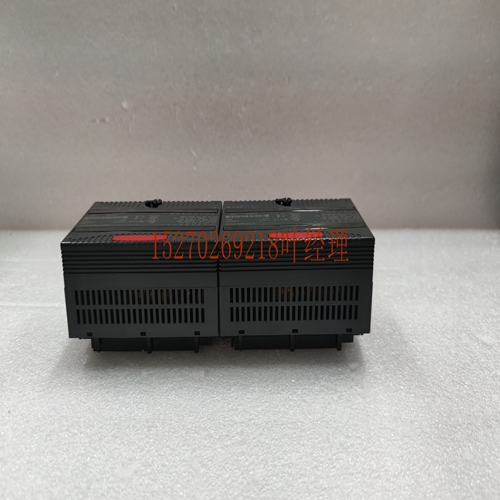
IS200TREGH5B工控模块卡件,电源模块
通过按光标移动(或箭头)键,可以将光标从一个字段移动到另一个字段。当您在要修改的字段中时,您可以键入您的选择或按Tab键滚动浏览可用的选项(或按Shift Tab键反转滚动方向)。te停止模式字段(HOLD或DEFLOW(DEFault LOW))中的条目决定了当模块从RUN(运行)切换到Stop(停止)模式时,s的行为。当此值设置为HOLD(默认值)时,s将保持其最后的状态。当您将此值更改为DEFLOW时,将变为零。其他配置注意事项%I大小中的条目只接受8、16和24,并且只接受%I地址。此字段确定返回给用户的位数。%AI Ref Adr的唯一允许条目是%AI地址。同样,%AQ Ref Adr的唯一允许条目是%AQ地址。每个报警的报警下限必须小于其相应的报警上限。%AI Ref Adr字段是%AI数据的参考地址,指向%AI内存中输入数据开始的位置的开始。每个都提供16位模拟数据作为0到32767或–32768到32767的整数值。取决于所选择的范围类型。%AQ Ref Adr字段是%AQ数据的参考地址,指向%AQ内存中数据到模块的起始位置。根据所选的范围类型,每个都提供16位模拟数据作为0到32767或–32768到32767的整数值。有关数据堡的详细信息,请参阅本章开头的Alog模块接口部分。IC693ALG442 Alog Combination I/O模块12 GFK–0898F第12章–IC693ALGA442 Along Combition I/O模块12-15%I状态信息%I Ref Adr是%I数据的参考地址,并指向%I存储器(即输入表)中报告模块状态信息的位置的开始。您可以通过编辑%I大小字段中的值来选择报告给PLC的%I状态位置的数量。“%I大小”字段中的允许值为8、16和24,表示报告给PLC的%I位置数。对于%I SIZE值为8或更大,返回的数据如下表所示。前八个%I位置-(可用于%I SIZE值8、16、24)%I位置描述%I模块正常-0表示T正常,1表示模块正常。%I+1用户电源正常-表示用户电源在指定范围内;当用户电源低于指定限制时读取0,当用户电源正常时读取1。%I+2和%I+3保留用于将来的模块。t在此模块中使用。%I+4到7见下面这些位的定义。%I+4到7(第一个%I字节的高位4位)保存一个错误代码,其定义如下:%I位数biry六分位错误0000 0错误0001 1 inlid 0010 2 inlid报警级别模块正常:0=模块故障0011 3 inlid斜坡时间或步骤1=模块正常1000 8 inlid E2功能用户电源正常1=用户供电正常0=用户供电不可用或未使用7–4 3 2 1 0错误代码:如果您发送反映inlid条件的E2数据,模块将触发comnd并返回第一个%I字节的高位4位中的错误代码。如果检测到错误,模块将停止标准操作;这些错误位用于用户信息,如果需要,可以触发。在您发送E2清除错误代码或重新配置模块之前,错误代码将一直持续。12 12-16系列90–30 PLC I/O模块规格–2000 GFK–0898F仅报告最近的错误;如果发生错误,现有错误代码将被覆盖。错误的优先级是:1。内置功能(最高优先级)2。Inlid。3.内置数据(斜坡或报警参数)(最低优先级)。因此,如果存在多个错误条件,则在错误代码中报告具有最高优先级的错误条件。第二个八个位置-(可用于%I SIZE值16、24)%I位置描述%I+8输入:通过%I+23为未来模块保留。可选择四个输入或范围中的一个;两个是电压范围。默认范围为0至+10V,其中输入或电压值范围为伏特。在输入模式下,它们向模块报告0到32767的整数值,而在模式下,0和32767之间的值被发送到模块。
You can move your cursor from field to field by pressing the Cursor Movement (or Arrow) keys. When you are in the field you want to modify, you can either type in your choice or press the Tab key to scroll through the ailable selections (or Shift-Tab to reverse the direction of the scrolling). te The entry in the Stop Mode field (HOLD or DEFLOW (DEFault LOW)) determines how the s will behave when the module is toggled from RUN to STOP mode. When this lue is set to HOLD (default), the s will retain their last state. When you change this lue to DEFLOW, the will go to zero. Other Configuration Considerations The entry in %I Size will only accept 8, 16 and 24, and will accept only %I addresses. This field detes the number of bits returned to the user. The only allowable entries for the %AI Ref Adr are %AI addresses. Similarly, the only allowable entries for the %AQ Ref Adr are %AQ addresses. The Alarm Low limit for each must be less than its corresponding Alarm High limit. The %AI Ref Adr field is the reference address for the %AI data and points to the start of the locations in the %AI memory where the input data to the module begins. Each provides 16 bits of alog data as an integer lue from 0 to 32,767 or –32768 to 32,767. depending on the range type selected. The %AQ Ref Adr field is the reference address for the %AQ data and points to the start of the locations in the %AQ memory where the data to the module begins. Each provides 16 bits of alog data as an integer lue from 0 to 32,767 or –32768 to 32,767, depending on the range type selected. For detailed infortion of the data fort, see the Interface to Alog Modules section at the beginning of this chapter. IC693ALG442 Alog Combition I/O Module 12 GFK–0898F Chapter12 – IC693ALG442 Alog Combition I/O Module 12-15 %I Status Infortion The %I Ref Adr is the reference address for the %I data and points to the start of the locations in the %I memory (that is, the Input Table) where status infortion from the module is reported. You can select the number of %I status locations reported to the PLC by editing the lue in the %I Size field. Allowable lues in the %I Size field are 8, 16, and 24 which refer to the number of %I locations reported to the PLC. For %I SIZE lues 8 or greater, the data brought back is in the fort described in the following tables. First eight %I locations - (ailable for %I SIZE lues 8, 16, 24) %I Locations Description %I Module OK - 0 indicates T OK, 1 indicates module OK. %I+1 User Supply OK - Indicates when user supply is in specified limits; reads a 0 when User supply below specified limit, 1 when User supply OK. %I+2 & %I+3 Reserved for future modules. t used in this module. %I+4 through 7 See definition for these bits below. %I+4through 7 (upper 4 bits of first %I byte) hold an error code which is defined as follows: %I bitnumber biry hexadecil error 0000 0 errors 0001 1 inlid 0010 2 inlid alarm level module ok: 0 = module failure 0011 3 inlid ramp time or step 1 = module OK 1000 8 inlid E2 function user power ok 1 = user supplied power OK 0 = user supplied power absent or t unused 7–4 3 2 1 0 error code: If the you send E2 data that reflects an inlid condition, the module will igre the comnd and return an error code in the upper 4 bits of the first %I byte. The module will T stop standard operation if an error is detected; these error bits are for the user’s infortion and can be igred if desired. The error code will rein until you send an E2 to clear the error code or reconfigure the module. 12 12-16 Series 90–30 PLC I/O Module Specifications – 2000 GFK–0898F Only the most recent error will be reported; an existing error code will be overwritten if ather error occurs. The priorities for errors are: 1. Inlid function (highest priority) 2. Inlid . 3. Inlid data (ramp or alarm parameter) (lowest priority). Thus, if multiple error conditions exist, the one with the highest priority is reported in the error code. Second eight locations - (ailable for %I SIZE lues 16, 24) %I Locations Description %I+8 Input: through %I+23 Reserved for future modules. t used in this module One of four input or ranges can be selected; two are voltage ranges. The default range is 0 to +10V, where input or voltage lues range from volts. In input mode they report 0 to 32767 integer lues to the and in mode lues between 0 and 32767 are sent to the module.


