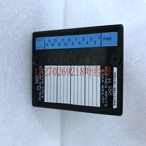
IS200TRLYH1F DCS工控模块备件
11 11-28 Series 90-30 PLC I/O Module Specifications–2000 GFK-0898F Selecting Ranges(11 11-28系列90-30 PLC输入/输出模块规格–2000 GFK–0898F选择范围)可按如下所述显示、选择或更改8个系列中每一个的范围。有两个电流和两个电压范围可供选择。初始显示R0:03 AO 1.00>S I16:I0017–I0032要显示范围,请按→→→. 显示屏将显示1(或当前选定的)和第一个可用范围。R0:03 AO 1.00>S CHAN 1:0–10 V您可以通过按±键切换各个范围。每个范围将显示如图所示。每个范围如下所示。将选择的范围是当前显示的范围。当屏幕上显示模块所需的范围时,按下ENT键即可接受。要返回上一屏幕,请按← 钥匙要查看下一个的范围显示,请按→ 钥匙R0:03 AO 1.00>S CHAN 2:0–10 V编辑此范围与第一次相同。所有活动的范围可以在同一行中更改。按下ENT键或按下← 键,直到显示初始屏幕。11 Alog模块GFK-0898F第11章–Alog模块11-29保存的配置包含8-Alog电流/电压模块的配置可以保存到EEPROM或MEM卡中,稍后从该设备读取到。包含这些配置的MEM卡和EEPROM可以读取到任何版本4或更高版本的Series 90-30中(不能读取到Series 90-20中)。有关保存和恢复操作的详细信息,请参阅手持式编程器用户手册第2章。11 11-30 Series 90-30 PLC I/O模块规格–2000 GFK-0898F IC693ALG392 Alog电流/电压框图下图是8-Alog电流-电压模块的框图。微处理器15V OPTO隔离系列90–30 PLC背板接口VLSI电压监控器EPROM RAM EEPROM LED 5V 15V D/A电流驱动器电压范围选择参考电源转换器+O O O O 24Vin ICOM FGND(X 8)输出VOUT VCOM a47037图11-18。8-Alog电流/电压模块框图-IC693ALG392 12节级1 1数字双级1表格_表级1 GFK-0898F 12-1第12章IC693ALGA442 Alog电流和电压组合输入/输出模块4输入/2 s-IC693A LG442 Alog电流/电压组合输入模块最多可提供4个差分输入电流或电压,2个单端电流和2个电流回路每一个都可以根据应用所需的电流或电压范围进行单独配置。除选择当前输入模式所需的跳线外,所有模块配置均通过软件完成。可使用Logicster 90-30/20/Micro编程软件配置器功能或Series 90-30手持式编程器配置所有量程。注意,在本模块的描述中,该模块将被简称为Alog Combo模块。每个模拟输入能够提供五个输入范围(两个电压和三个电流),分别为:0至+10伏(单极)-输入和s的默认范围。–10至+10伏特(双极)增强。默认输入范围为电压模式0至+10V(单极),用户数据按比例缩放,0V对应于0的计数,10V对应于32767的计数。
11 11-28 Series 90-30 PLC I/O Module Specifications – 2000 GFK-0898F Selecting Ranges The range for each of the 8 s can be displayed and selected or changed as described below. There are two current and two voltage ranges that can be selected. Initial Display R0:03 AO 1.00 >S I16:I0017–I0032 To display the ranges press →→→. The display will show 1 (or the currently selected ) and the first ailable range. R0:03 AO 1.00 >S CHAN 1: 0 – 10 V You can toggle through the range for each by pressing the ± key. Each range will be displayed as shown. Each of the ranges are shown below. The range that will be selected is the one currently displayed. When the desired range for the module is displayed on the screen it can be accepted by pressing the ENT key. To return to the previous screen, press the ← key. To view the next ’s range display, press the → key. R0:03 AO 1.00 >S CHAN 2: 0 – 10 V Edit this ’s range the same as you did for the first . The range of all active s can be changed in the same nner. Return to the initial display screen by pressing the ENT key or by pressing the ← key until the initial screen is displayed. 11 Alog Modules GFK-0898F Chapter 11 – Alog Modules 11-29 Saved Configurations Configurations that contain an 8- Alog Current/Voltage module can be saved to an EEPROM or MEM card and read from that device into the at a later time. MEM cards and EEPROMs containing these configurations can be read into any Release 4 or later Series 90-30 (cant be read into a Series 90-20 ). Refer to Chapter 2 of the Hand-Held Programmer User’s nual for detailed infortion on the Save and Restore operations. 11 11-30 Series 90-30 PLC I/O Module Specifications – 2000 GFK-0898F IC693ALG392 Alog Current/Voltage Block Diagram The following figure is a block diagram of the 8- Alog Current/Voltage Module. MICRO PROCESSOR 15V OPTO ISOLATION SERIES 90–30 PLC BACKPLANE BACKPLANE INTERFACE VLSI VOLTAGE SUPERVISOR EPROM RAM EEPROM LEDs 5V 15V D/A CURRENT DRIVER VOLTAGE RANGE SELECT REFERENCE POWER CONVERTER + O O O O O O 24Vin ICOM FGND ( X 8 ) Iout VOUT VCOM a47037 Figure 11-18. 8- Alog Current/Voltage Module Block Diagram - IC693ALG392 12 section level 1 1 figure bi level 1 table_big level 1 GFK-0898F 12-1 Chapter 12 IC693ALG442 Alog Combition I/O Module Alog Current/Voltage Combition Module 4 Input/2 s - IC693ALG442 The Alog Current/Voltage Combition Input/ module provides up to 4 differential input current or voltage s and 2 single-ended s with either current loop s or voltage s. Each can be individually configured for the current or voltage range, as applicable, required for your application. All module configuration is done through software, except for a jumper required for selecting the current input mode. All ranges can be configured using either the Logicster 90-30/20/Micro programming software configurator function or the Series 90-30 Hand-Held Programmer. te that in this module’s description, the module will be simply referred to as the Alog Combo Module. Each alog input is capable of providing five input ranges (two voltage and three current), which are: 0 to +10 volts (unipolar) - default range for both input and s. –10 to +10 volts (bipolar) Enhanced The default input range is voltage mode 0 to +10 volts (unipolar) with user data scaled so that 0V corresponds to a count of 0 and 10V corresponds to a count of 32767.


