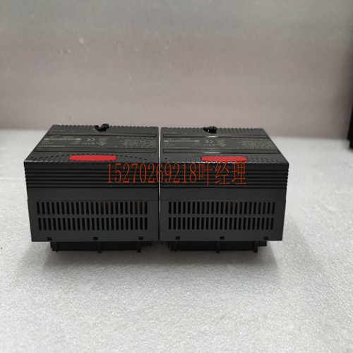
IS200TRPAH1A控制模块
使用的参考值系统中可安装的8 Alog电流/电压模块的数量取决于可用的%AQ和%I参考值的数量。每个模块使用8%的AQ参考(取决于ebled的数量)和8或16%的I参考(取决开放检测配置)。311型、313型和323型系统中有32%的AQ参考可用,331型系统中64%的AQ引用可用,340型和341型系统中256%的AQ可用,351型和352型系统中可用的512%AQ参考值11 Alog模块GFK-0898F第11章–Alog模块11-17可安装在系统中的8个Alog电流/电压模块的数量为:在使用311、313、313和313型的系统中,在使用331型32的系统中,在使用340型和341型64的系统中使用350–364型其他配置注意事项在为应用程序规划模块配置时,还必须考虑已安装电源的负载容量以及安装在基板中的所有模块的总负载要求。有关电源、基板和模块负载要求的详细信息,请参阅本手册第1章。下表列出了该模块的技术规格。除非另有说明,否则测试条件为:环境温度为25C(77F)时,VUSER=24。11 11-18 Series 90-30 PLC I/O模块规格–2000 GFK-0898F表11-5。IC693ALG392规格数量1至8可选,单端电流范围和电压范围V,-10至+10 V校准工厂校准至0.625µA,适用于0至20;0.5µA,适用于4-20;对于电压(每计数),3125表示用户电源电压(mil)+24,来自用户提供的电压源外部电源电压范围电源抑制比(PSRR)1电流电压20至30 5µA/V(典型值),10µA/V 25/V(典型),50/V外部电源电压纹波10%来自PLC背板的内部电源电压+5更新率8毫秒(大约,所有8秒)由I/O扫描时间确定,并且依赖于应用。分辨率:0.5µA(1 LSB=0.5µA).625µA(2 LSB=.625µB)V3125(1 LSB=.3125)–10至+10 V.3125(1 LSAB=.3125)绝对精度:3电流模式:25(77°F)时满量程的±0.1%,25(77℉)时满刻度的典型±0.25%,工作温度范围内满刻度的±0.5%电压模式25(77℃)时满标度的±0.25%,25(75℉)时全标度的典型±0.5%,工作温度范围内满量程的±1.0%符合电压VUSER–3V(最小值)至VUSER用户负载(电流模式)0至850Ω (VUSER=20V、1350时的最小值Ω VUSER=30V时)2负载电容(电流模式)2000 pF负载电感(电流模式。1 PSSR通过将VUSER从24V干燥到30V来测量。2负载小于800Ω 取决于温度。3在存在严重RF干扰(IEC 801-3,10V/m)的情况下,对于电流s,精度可能降低到±1%FS,对于电压s,精度降低到±3%FS。11 Alog模块GFK-0898F第11章–Alog模块11-19 8 Alog模块环境温度的降额曲线12345678 ACTIVE s短路负载VUSER=26.5V(电流模式)1200 ohm负载1000 ohm负载250 ohm负载短路负载800 ohm负载500 ohm负载250ohm负载TE对于性能和模块寿命,建议模块在负载电阻下运行,以从模块卸载热量。环境温度VUSER=30V(混合电压和电流)表示所用电压的数量,然后加上电流的数量。这是所用的总数量。要确定工作温度,请选择使用的总有效s(从图表底部),然后在电压s数的直线上画一条垂直线。
References Used The number of 8- Alog Current/Voltage modules which y be installed in a system depends on the amount of %AQ and %I references ailable. Each module uses 8 %AQ references (depending on the number of s ebled) and 8 or 16 %I references (depending on open detect configuration). There are 32 %AQ references ailable in a Model 311, Model 313, and Model 323 system, 64 %AQ references ailable in a Model 331 system, 256 %AQ references ailable in a Model 340 and Model 341 system, and 512 %AQ references ailable in a Model 351 and Model 352 system 11 Alog Modules GFK-0898F Chapter 11 – Alog Modules 11-17 The number of 8- Alog Current/Voltage modules that can be installed in a system are: 4 in a system using Models 311, 313, or 323 8 in a system using Model 331 32 in a system using Models 340 and 341 64 in a system using Models 350 – 364 Other Configuration Considerations When planning the module configuration for your application you must also consider the load capacity of the installed power supply and the total load requirements of all modules that are installed in the baseplate. Refer to Chapter 1 in this nual for details on power supply, baseplate, and module load requirements. The following table lists the specifications for this module. te that test conditions, unless otherwise ted, are: VUSER = 24 at an ambient temperature of 25C (77F). 11 11-18 Series 90-30 PLC I/O Module Specifications – 2000 GFK-0898F Table 11-5. Specifications for IC693ALG392 Number of s 1 to 8 selectable, single-ended Current Range and Voltage Range V and –10 to +10 V Calibration Factory calibrated to .625µA for 0 - 20 ; 0.5µA for 4 - 20 ; and .3125 for voltage (per count) User Supply Voltage (mil) +24 , from user supplied voltage source Exterl Supply Voltage Range Power Supply Rejection Ratio (PSRR) 1 Current Voltage 20 to 30 5 µA/V (typical), 10 µA/V 25 /V (typical), 50 /V Exterl Power Supply Voltage Ripple 10% Interl Supply Voltage +5 from PLC backplane Update Rate 8 msec (approxite, all eight s) Determined by I/O scan time, and is application dependent. Resolution: 0.5 µA (1 LSB = 0.5 µA) .625 µA (1 LSB = .625 µA) V .3125 (1 LSB = .3125 ) –10 to +10 V .3125 (1 LSB = .3125 ) Absolute Accuracy: 3 Current Mode ± 0.1% of full scale @ 25 (77°F), typical ± 0.25% of full scale @ 25 (77°F), ± 0.5% of full scale over operating temperature range Voltage Mode ± 0.25% of full scale @ 25 (77°F), typical ± 0.5% of full scale @ 25 (77°F), ± 1.0% of full scale over operating temperature range Compliance Voltage VUSER –3V (minimum) to VUSER User Load (current mode) 0 to 850Ω (minimum at VUSER = 20V, 1350Ω at VUSER = 30V) 2 Load Capacitance (current mode) 2000 pF Load Inductance (current mode) 1 H Loading (voltage mode) load Capacitance 5 (2K ohms minimum resistance) (1 µF capacitance) Isolation 1500 volts between field and logic side Interl Power Consumption 110 from +5V PLC backplane supply 315 from +24V user supply Refer to Appendix C for product standards and general specifications. 1 PSSR is measured by rying VUSER from 24V to 30V. 2 Load less than 800 Ω is temperature dependent. 3 In the presence of severe RF interference (IEC 801-3, 10V/m), accuracy y be degraded to ±1% FS for current s and ±3% FS for voltage s. 11 Alog Modules GFK-0898F Chapter 11 – Alog Modules 11-19 Derating Curves for the 8 Alog Module AMBIENT TEMPERATURE 12345678 ACTIVE S Shorted loads VUSER = 26.5V (CURRENT MODE) 1200 ohm loads 1000 ohm loads 250 ohm loads shorted loads 800 ohm loads 500 ohm loads 250 ohm loads TE For perfornce and module life, it is recommended that the module be operated at load resistance to offload heat from the module. AMBIENT TEMPERATURE VUSER = 30V (MIXED VOLTAGE AND CURRENT) the line for the number of voltage s used, then add the number of current s. This is the total number of s used. To determine the operating temperature, select the total active s used (from the bottom of chart), then draw a vertical line to the line for the number of voltage s.


