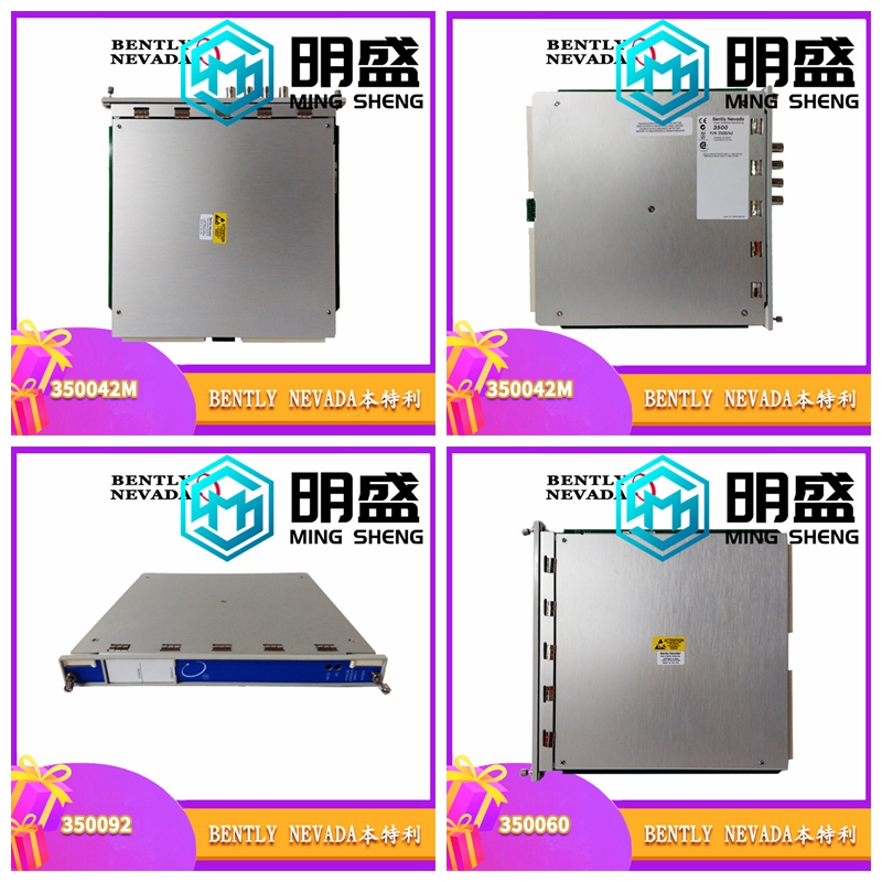
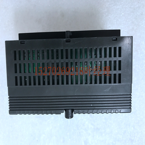
IS200TRPGH1A系统模块卡件,处理器卡件
可使用Logicster 90-30/20/Micro或CIMPLICITY控制编程软件配置器功能或Series 90-30手持式编程器配置所有范围。默认范围为0至+10伏。可配置的电流和电压范围为:0至+10伏(单极)–10至+10伏特(双极)毫安每一个都能够将15至16位(取决于所选范围)的二进制(数字)数据转换为模拟,以供您的应用所需。每12毫秒更新一次所有八个。%AQ寄存器中的用户数据处于16位2的补码状态。在当前模式下,每个都会向报告开路故障。当系统电源中断时,模块可以进入kwn最后状态。只要将用户电源应用于模块,每个模块都将保持其最后一个值,或重置为零,这取决于您如何配置模块。重要产品信息请提供以下重要产品信息。此版本的8-Alog电流/电压模块需要以下产品版本才能兼容::固件版本3.3至4.6:如果您的固件版本为3.3至4.6,则必须在配置时选择16%I位。如果此选择被取消,则会发生模块丢失故障。:固件版本5.0或更高版本:如果您的固件版本5.0,或更高,则%I配置将接受8或16%I位。Logicster 90-30/20/Micro Software:5.00版或更高版本需要使用Logicster 90-20/20/Micro软件组态功能组态模块。控制软件:使用控制软件配置功能配置模块需要2.00版或更高版本。11 11-12 Series 90-30 PLC I/O模块规格–2000 GFK-0898F IC693ALG392电流/电压范围和模式电流操作范围内的用户数据按比例缩放,使4对应于计数0,20对应于计数32000。在该范围内,用户数据被缩放,使得0对应于0的计数,20对应于32000。注意,在该模式下,您可以输入一个高达32767的值,提供大约20.5的值。该范围和范围的电流比例如下所示。在当前模式下,模块还提供开环故障检测,并在%I表中报告给PLC。4%AQ(分)电流A4683 0 20 0 32000范围%AQ(分)当前a44684 0 20 0 3200范围图11-13。电流电压操作的缩放对于默认单极模式(0至+10伏)下的电压操作,缩放用户数据,以使0伏对应于0的计数,+10伏对应于32000的计数。在此模式下,您最多可以输入32767,以获得大约10.24伏的超范围。在–10至+10伏范围内,用户数据被缩放,因此–10伏对应于–32000的计数,+10伏对应于+32000的计数。在此范围内,您可以输入-32767到+32767,以获得大约-10.24伏到+10.24伏的超范围。0至+10伏范围和-10至+10伏特范围的电压比例如下图所示。%AQ(分升)电压(V)0 a4658 10 10 32000 32000 0双极模式%AQ(分升)电压值(V)a45718 0 10 32000单极模式0图11-14。电压11 Alog模块的缩放GFK-0898F第11章–Alog模块11-13与8-Alog电流/电压模块的接口Series 90-30 PLC使用%AQ数据表中的数据记录可编程控制器使用的模拟值。8-Alog电流/电压模块的方案如下所示。有关模拟模块接口的更多信息,请参阅本章开头部分。
All ranges can be configured using either Logicster 90-30/20/Micro or CIMPLICITY Control Programming Software configurator function, or the Series 90-30 Hand-Held Programmer. The default range is 0 to +10 volts. Configurable current and voltage ranges are: 0 to +10 volts (unipolar) –10 to +10 volts (bipolar) milli milli Each is capable of converting 15 to 16 bits (depending on the range selected) of biry (digital) data to an alog for use as required by your application. All eight s are updated every 12 milliseconds. User data in the %AQ registers is in a 16-bit 2’s complement fort. In current modes, an open- fault is reported to the for each . The module can go to a kwn last state when system power is interrupted. As long as user power is applied to the module, each will intain its last lue, or reset to zero, as determined by how you have configured the module. Important Product Infortion Please te the following important product infortion. This version of the 8- Alog Current/Voltage module requires the following product versions for compatibility: : Firmware Versions 3.3 to 4.6: If your has firmware version 3.3 to 4.6, you must select 16 %I bits at configuration. If this selection is t de, a loss of module fault will occur. : Firmware Version 5.0 or later: If your has firmware version 5.0, or later, then the %I configuration will accept 8 or 16 %I bits. Logicster 90-30/20/Micro Software: Version 5.00, or later, is required to configure the module using the Logicster 90-30/20/Micro software configuration function. Control Software: Version 2.00, or later, is required to configure the module using the Control software configuration function. 11 11-12 Series 90-30 PLC I/O Module Specifications – 2000 GFK-0898F IC693ALG392 Current/Voltage Ranges and Modes Current Operation In the range user data is scaled so that 4 corresponds to a count of 0 and 20 corresponds to a count of 32000. In the range, user data is scaled so that 0 corresponds to a count of 0 and 20 corresponds to 32000. te that in the mode, you can enter a lue up to 32767 which provides a of approxitely 20.5 . Scaling of the current for both the range and the range is shown below. In current mode the module also provides an open loop fault detect which is reported to the PLC in the %I table. 4 %AQ (decil) CURRENT a44683 0 20 0 32000 Range %AQ (decil) CURRENT a44684 0 20 0 32000 Range Figure 11-13. Scaling for Current Voltage Operation For Voltage Operation in the default unipolar mode (0 to +10 volts), user data is scaled so that 0 volts corresponds to a count of 0 and +10 volts corresponds to a count of 32000. In this mode, you can enter up to 32767 for an overrange of approxitely 10.24 volts . In the –10 to +10 volt range user data is scaled so that –10 volts corresponds to a count of –32000 and +10 volts corresponds to a count of +32000. In this range, you can enter –32767 to +32767 for an overrange of approxitely –10.24 volts to +10.24 volts. Scaling of the voltage for both the 0 to +10 volt range and the –10 to +10 volt range is as shown in the following figure. %AQ (decil) VOLTAGE (V) 0 a44658 10 10 32000 32000 0 Bipolar Mode %AQ (decil) VOLTAGE (V) a45718 0 10 32000 Unipolar Mode 0 Figure 11-14. Scaling for Voltage 11 Alog Modules GFK-0898F Chapter 11 – Alog Modules 11-13 Interface to the 8- Alog Current/Voltage Module The Series 90-30 PLC uses the data within the %AQ data table to record alog lues for use by the programble controller. This scheme for the 8- Alog Current/Voltage module is shown below. More infortion on the interface to alog modules can be found at the beginning of this chapter.


