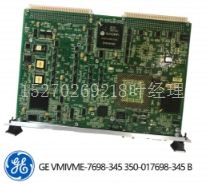
IS200TRPGH1B机器人模块卡件
Alog电流模块规范-IC693ALG391电流范围和电压范围1 1至5 V和0至5 V校准工厂校准至每计数4µA电源电压(mil)+24,来自背板或用户提供的电压源上的隔离+24,背板外部电源电压范围为2 20至30外部电源电压纹波10%更新率5毫秒(两者都近似),由I/O扫描时间确定,取决于应用。合规电压25 V用户负载(电流模式)0至850 ohms负载电容(电流模式标准和通用规范。1可根据图3-38所示的总模块电流计算电压选项的允许负载。2允许用户供电取决于当前负载和环境温度,如图3-38所示。3在存在严重射频干扰(IEC 801-3,10V/m)的情况下,精度可能会降低到µA(范围),µA(量程)。11 11-8 Series 90-30 PLC I/O模块规格–2000 GFK-0898F,根据。示例:两个S均处于0至+10V模式,2K负载=51图11-9。负载电流降额IC693ALG391 Alog电流框图下图是2-Alog模块的框图。IN24V IN0V 2–偏置和双参考发电机OS2 OS1 a4556 FB CH1 FB CH2 VOUT2 0V VOUT1 RTN2 RTN1 24V IOUT2 IOUT1 JMPV1 JMPV2 2–电流驱动器GND1 GND2 VREF1 VREF2 DEFO/默认为零选择跳线1 0–20选择跳线2 0–20选择器跳线RAN1A RAN1B RAN2B RAN2A机架接地0V+5V+10V–10V 10 250 10 D3–D14(共2位)双D/A ICH1 ICH2 I24V点火CLK D FF CLR Q/DO(CS1)+5V IOWT IOCLK IODT RUN EN PSOK L5V LGND BID4 BID2背板接口和隔离RY逆变器调节器和电压监控器RST/0V PWR KILL+5V+10V–10V–24V POT调节器(根据OCS图11-10)。Alog电流模块框图-IC693ALG391 11 Alog模块GFK-0898F第11章-Alog模块11-9 IC693ALGA391 Alog模块现场接线图以下两幅图提供了将现场接线连接至Alog电流模件的信息。图3-40显示了用作模拟电流所需的连接。IOUT2 GND TERMILS现场布线现场布线-模拟电流模块(电流模式)-IC693ALG391 te可使用外部电源为模块和回路电流供电。有关接线和屏蔽接地连接的详细信息,请参阅第2章。11 11-10 Series 90-30 PLC I/O模块规格–2000 GFK-0898F图3-41显示了模块用作模拟电压所需的连接。**VOUT2 IOUT1 IOUT2 VOUT1 GND TERMILS现场接线连接,请参阅文本24V*RTN1 JMPV1 JMPV2 DEF 0*RANGE 1**RANGE 2 2K(MIN)2K(MAX)RTN2+图11-12。现场接线-Alog电流模块(电压模式)-IC693ALG391 te有关接线和屏蔽接地连接的详细信息,请参阅第2章。11 Alog模块GFK-0898F第11章–Alog模块11-11 Alog电流/电压-8 IC693ALG392 8-Alog电流和电压模块最多可提供八个单端电流回路或电压。每个Alog可提供两个电流范围或两个电压范围。每个都可以针对应用程序所需的范围单独配置。模块具有用于配置的跳线或开关。
Table 11-3. Specifications for Alog Current Module - IC693ALG391 Current Range and Voltage Range 1 1 to 5 V and 0 to 5 V Calibration Factory calibrated to 4µA per count Supply Voltage (mil) +24 , from isolated +24 on backplane or user supplied voltage source, and +5 from backplane Exterl Supply Voltage Range 2 20 to 30 Exterl Supply Voltage Ripple 10% Update Rate 5 msec (approxite, both s) Determined by I/O scan time, and is application dependent. Compliance Voltage 25 V User Load (current mode) 0 to 850 ohms Load Capacitance (current mode) 2000 pF Load Inductance (current mode) 1 H Loading (voltage mode) 5 (2K ohms minimum resistance) (2000 pF capacitance) Isolation 1500 volts between field and logic side Interl Power Consumption 30 from +5V supply 215 from Isolated +24 backplane supply or user supply Refer to Appendix B for product standards and general specifications. 1 Allowable load on the voltage option can be calculated from the total module current shown in Figure 3-38. 2 Allowable user supply is dependent on the current load and the ambient temperature as shown in Figure 3-38. 3 In the presence of severe RF interference (IEC 801-3, 10V/m), accuracy y be degraded to µA ( range), µA ( range). 11 11-8 Series 90-30 PLC I/O Module Specifications – 2000 GFK-0898F IN ADDITION TO VOUT LOAD CURRENT PER . EXAMPLE: BOTH S IN 0 TO +10V MODE WITH 2K LOADS = 51 Figure 11-9. Load Current Derating IC693ALG391 Alog Current Block Diagram The following figure is a block diagram of the 2- Alog module. IN24V IN0V 2– OFFSET AND DUAL REFERENCE GENERATOR OS2 OS1 a44556 FB CH1 FB CH2 VOUT2 0V VOUT1 RTN2 RTN1 24V IOUT2 IOUT1 JMPV1 JMPV2 2– CURRENT DRIVER GND1 GND2 VREF1 VREF2 DEFO / DEFAULT TO ZERO SELECT JUMPER 1 0–20 SELECT JUMPER 2 0–20 SELECT JUMPER RAN1A RAN1B RAN2B RAN2A FRAME GROUND 0V +5V +10V –10V 10 250 250 10 D3–D14 (GNITUDE 2 BITS) DUAL D/A ICH1 ICH2 I24V IGND CLK D FF CLR Q/ DO (CS1) +5V IOWT IOCLK IODT RUN EN PSOK L5V LGND BID4 BID2 BACKPLANE INTERFACE AND ISOLATION RY INVERTER REGULATOR AND VOLTAGE SUPERVISOR RST/ 0V PWR KILL +5V +10V –10V –24V POT ADJUST (2 PER ) OCS Figure 11-10. Alog Current Module Block Diagram - IC693ALG391 11 Alog Modules GFK-0898F Chapter 11 – Alog Modules 11-9 IC693ALG391 Alog Module Field Wiring Diagrams The following two figures provide infortion for connecting field wiring to the Alog Current module. Figure 3-40 shows the connections necessary for the s to be used as alog current s. IOUT2 GND TERMILS FIELD WIRING Field Wiring - Alog Current Module (Current Mode) - IC693ALG391 te An exterl supply can be used to power the module and the loop current. Please refer to Chapter 2 for wiring and shield ground connection details. 11 11-10 Series 90-30 PLC I/O Module Specifications – 2000 GFK-0898F Figure 3-41 shows the connections necessary for the s of the module to be used as alog voltage s. * * VOUT2 IOUT1 IOUT2 VOUT1 GND TERMILS FIELD WIRING CONNECTION, REFER TO TEXT 24V * RTN1 JMPV1 JMPV2 DEF 0 * RANGE 1 * * RANGE 2 2K (MIN) 2K (MIN) RTN2 + Figure 11-12. Field Wiring - Alog Current Module (Voltage Mode) - IC693ALG391 te Please refer to Chapter 2 for wiring and shield ground connection details. 11 Alog Modules GFK-0898F Chapter 11 – Alog Modules 11-11 Alog Current/Voltage - 8 IC693ALG392 The 8- Alog Current/Voltage module provides up to eight single-ended s with current loop s or voltage s. Each alog is capable of providing two current ranges or two voltage ranges. Each can be individually configured for the range required for your application. The module has jumpers or switches for configuration.


