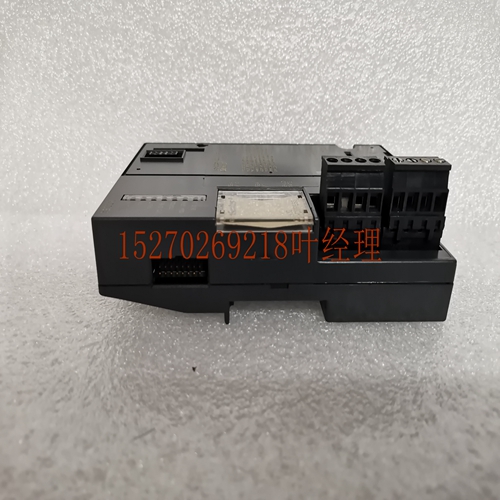
IS200TRPGH2B处理器模块,工控模块系统备件
电压处于与电流相对应的VOUTx。电流或电压的选择通过I/O端子板上的跳线取消。如果安装了跳线,则模块作为电流源运行。如果存在JMPVx跳线,则模块作为电压源运行。每个都有选择电压或电流的选项。电流范围的设置决定了电压范围。通过使用250欧姆电阻器代替从JMPVx到IOUTx的电压跳线,可以增加电压范围。下表显示了范围设置与电压s之间的关系。表11-2。范围设置与电压范围设置电压范围(范围跳线)1至5 V 2至10 V,带外部电阻器(存在范围跳线)0至5 V带外部电阻器模块的主要电源为PLC电源提供的隔离+24电源。模块的I/O端子板上还提供了两个端子,供用户提供+24伏电压。这允许您提供一个备用电源,以便在间隔电源丢失且选择了“保持最后状态”时,可以继续保持其值。您还需要提供模块电压,以降低PLC隔离+24电源的负载。当所施加的电压高于隔离的+24电源时,将使用用户电源,该电压范围为21.5伏至26.5伏。模块中产生约+24V的中间电压源,以驱动电流回路s。模块上的电流回路驱动器为源极型驱动器。这意味着正电流从电流回路流出,以便用户的负载可以返回。电阻器与回路串联,以限制接地回路电流。为了最大限度地减少%AQ(分)电流范围A4684 0 20 0 32000 11 Alog模块GFK-0898F第11章–Alog模块11-7电容负载和ise,应使用良好等级的绞合屏蔽仪表电缆连接模块的所有现场连接。屏蔽应连接到用户终端连接器块上的GND。GND连接提供对基板(框架接地)的访问,从而对任何屏蔽漏极电流造成的噪声产生良好的抑制。当模块电源工作时,模块面板上的LED亮起。该模块通过使用光学隔离在现场布线和背板之间提供外部产生的电隔离。该模块可安装在Series 90-30 PLC系统中5或10插槽基板的任何I/O插槽中。如果不使用用户提供的电源为模块供电,则可在基板中安装三个Alog Current模块。
A voltage is at VOUTx that corresponds to the current . The selection of current or voltage is de with a jumper on the I/O termil board. If jumper is installed, the module performs as a current source. If the JMPVx jumper is present, the module performs as a voltage source. Each has the option of selecting voltage or current. The setting of the current range determines the voltage range. The voltage range can be increased by using a 250 ohm resistor in place of the voltage jumper from JMPVx to IOUTx. The following table shows the relationship between range settings and voltage s. Table 11-2. Range Settings vs. Voltage s Range Setting Voltage Range ( range jumper) 1 to 5 V 2 to 10 V with exterl resistor (range jumper present) 0 to 5 V V with exterl resistor The priry power source for the module is the isolated +24 power supplied by the PLC power supply. Two termils are also provided on the module’s I/O termil board for user supplied +24 volts. This allows you to provide a standby power supply so that the s can continue to hold their lue if the interl supply is lost and Hold-Last-State is selected. You y also want to supply the module voltage to reduce the load on the PLC isolated +24 power supply. The user supply will be used when the applied voltage is higher than the isolated +24 supply, which can range from 21.5 volts to 26.5 volts. An interl voltage source of about +24V is generated in the module to drive the current loop s. The current loop drivers on the module are source type drivers. This means that a positive current flows out of the current loop s so that the user’s loads can be returned to . A resistor is placed in series with the return to limit ground loop currents. To minimize the %AQ (decil) CURRENT RANGE a44684 0 20 0 32000 11 Alog Modules GFK-0898F Chapter 11 – Alog Modules 11-7 capacitive loading and ise, all field connections to the module should be d using a good grade of twisted, shielded instrumentation cable. The shields should be connected to GND on the user termil connector block. The GND connection provides access to the baseplate (frame ground) resulting in superior rejection of ise caused by any shield drain currents. An LED on the module’s faceplate is ON when the module’s power supply is operating. The module provides electrical isolation of exterlly generated ise between field wiring and the backplane through use of optical isolation. This module can be installed in any I/O slot of a 5 or 10-slot baseplate in a Series 90-30 PLC system. If user provided supplies are t used to power the module, a of three Alog Current modules can be installed in a baseplate.


