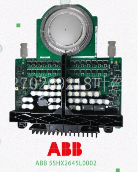
IS200TRPSH1A工控备件模块
90-30系列PLC背板微处理器XTAL图10-18。16-Alog电流输入模块框图-IC693ALG223 11节级1 1数字双级1表_big级1 GFK-0898F 11-1第11章Alog模块Alog电压-2 IC693ALGA390 Series 90-30可编程逻辑控制器的2-Alog电压模块提供两个,每个模块能够将13位二进制(数字)数据转换为模拟,以便根据应用程序的需要使用。Alog电压模块能够提供-10至+10伏范围内的电压。转换后的sigl的分辨率是12位biry加号,实际上是13位(8192中的1部分)。每次扫描时(约5毫秒)都会更新这两个。%AQ寄存器中的用户数据处于16位2的补码状态。%AQ寄存器中的13个最高有效位由PLC转换为符号数量,并发送至模块供D/A转换器ry使用。转换为符号量的13个位的位置如下所示。电压与D/A转换器数据之间的关系如图3-30所示。S D11 D10 D9 D8 D7 D6 D5 D4 D3 D2 D1 D0 X X MSB LSB S=符号位。X=t适用于本讨论。D/A位(分)电压(V)0 a4657 10 10 4000 4000 0图11-1。D/A位与电压如果进入停止模式或复位,模块的状态可以是默认为0伏或保持最后状态。通过在模块上的可拆卸端子连接器上配置DEF0跳线,可以选择所需的状态。如果未安装跳线,将在STOP(停止)或RESET(复位)时保持最后状态。的缩放比例如下所示。11 11-2 90-30系列PLC I/O模块规格–2000 GFK-0898F%AQ(分)电压(V)0 a4658 10 10 32000 32000 0图11-2。电压缩放模块的主要电源是由PLC电源提供的隔离+24电源。模块端子连接器上提供两个端子,供用户提供+24伏电压。这允许您提供一个备用电源,这样,如果中断电源并选择了“保持最后状态”,则可以继续保持其值。此外,您还可以提供模块电压,以降低PLC隔离+24电源的负载。当施加的电压比隔离+24电源高0.7伏时,必须使用用户电源,该电压范围为21.5伏至26.5伏。当模块电源工作时,模块面板顶部的LED亮起。为了最大限度地减少电容负载和噪声,所有现场连接应使用良好等级的绞合屏蔽仪表电缆。屏蔽应连接到用户终端连接器块上的GND。GND连接提供对基板(框架接地)的访问,从而对任何屏蔽漏极电流造成的噪声产生良好的抑制。该模块通过使用光学隔离在现场布线和背板之间提供外部产生的电隔离。该模块可安装在Series 90-30 PLC系统中5或10插槽基板的任何I/O插槽中。请参阅第3-11页,以确定系统中可安装的Alog Voltage模块的数量。表11-1。Alog电压模块规格,IC693ALG390电压范围–10至+10伏校准工厂校准至2.5每计数电源电压(mil)+24,来自底板上的隔离+24或用户提供的电压源,背板外部电源电压范围18至30外部电源电压波动10%更新率5毫秒(两者都是)。由于更新率由I/O扫描时间决定,且取决于应用程序,因此更新率接近。分辨率负载5(最小电阻2K欧姆)负载电容2000皮法,场侧和逻辑侧之间隔离1500伏互锁功耗32来自+5伏电源120来自+24伏电源(隔离背板或用户电源)请参阅附录B了解产品标准和一般规范。
SERIES 90-30 PLC BACKPLANE MICRO PROCESSOR XTAL Figure 10-18. 16- Alog Current Input Module Block Diagram - IC693ALG223 11 section level 1 1 figure bi level 1 table_big level 1 GFK-0898F 11-1 Chapter 11 Alog Modules Alog Voltage - 2 IC693ALG390 The 2- Alog Voltage module for the Series 90-30 Programble Logic Controller provides two s, each capable of converting 13 bits of biry (digital) data to an alog for use as required by your application. The Alog Voltage module is capable of providing s in the range of –10 to +10 volts. Resolution of the converted sigl is 12 bits biry plus sign which is effectively 13 bits (1 part in 8192). Both s are updated on every scan (about 5 milliseconds). User data in the %AQ registers is in a 16-bit 2’s complement fort. The 13 most significant bits from the %AQ register are converted to sign gnitude by the PLC and sent to the module for use by the D/A converter ry. The placement of the 13 bits converted to sign gnitude is shown below. The relationship between the voltage and the data from the D/A converter is shown in Figure 3-30. S D11 D10 D9 D8 D7 D6 D5 D4 D3 D2 D1 D0 X X X MSB LSB S = Sign bit. X= t applicable to this discussion. D/A BITS (decil) VOLTAGE (V) 0 a44657 10 10 4000 4000 0 Figure 11-1. D/A Bits vs. Voltage The state of the module, if the goes to the STOP mode or RESET, can be either Default to 0 volts or Hold-Last-State. Selection of the desired state is de by configuring the DEF0 jumper on the detachable termil connector on the module. If the jumper is t installed, the s will Hold-Last-State on STOP or RESET. Scaling of the is shown below. 11 11-2 Series 90-30 PLC I/O Module Specifications – 2000 GFK-0898F %AQ (decil) VOLTAGE (V) 0 a44658 10 10 32000 32000 0 Figure 11-2. Scaling for Voltage The priry power source for the module is the isolated +24 power supplied by the PLC power supply. Two termils are provided on the module’s termil connector for user supplied +24 volts. This allows you to provide a standby power supply, so that the s can continue to hold their lue if the interl supply is lost and Hold Last State is selected. Additiolly, you can also supply the module voltage to reduce the load on the PLC isolated +24 power supply. The user supply must be used when the applied voltage is 0.7 volts higher than the isolated +24 supply, which can range from 21.5 volts to 26.5 volts. An LED at the top of the module’s faceplate is ON when the module’s power supply is operating. To minimize capacitive loading and ise, all field connections should be d using a good grade of twisted, shielded instrumentation cable. The shields should be connected to GND on the user termil connector block. The GND connection provides access to the baseplate (frame ground) resulting in superior rejection of ise caused by any shield drain currents. The module provides electrical isolation of exterlly generated ise between field wiring and the backplane through the use of optical isolation. This module can be installed in any I/O slot of a 5 or 10-slot baseplate in a Series 90-30 PLC system. Refer to page 3-11 to determine the number of Alog Voltage modules that can be installed in a system. Table 11-1. Specifications for Alog Voltage Module, IC693ALG390 Voltage Range –10 to +10 volts Calibration Factory calibrated to 2.5 per count Supply Voltage (mil) +24 , from isolated +24 on backplane or user supplied voltage source, and +5 from backplane Exterl Supply Voltage Range 18 to 30 Exterl Supply Voltage Ripple 10% Update Rate 5 msec (both s) This update rate is approxite since it is determined by I/O scan time, and is application dependent. Resolution Loading 5 (2K ohms minimum resistance) Load Capacitance 2000 pico farads, Isolation 1500 volts between field side and logic side Interl Power Consumption 32 from +5 volt supply 120 from +24 volt supply (isolated backplane or user supply) Refer to Appendix B for product standards and general specifications.


