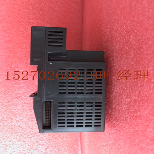
IS200TRTDH1CEX系统模块卡件
Alog输入模块10 GFK-0898F第10章–Alog输入模件10-33表10-9。配置参数说明参数说明激活输入一个从1*到16的数字。此数字表示要转换的数量。以连续的顺序扫描。1是第一次扫描。如果选择了八个以上,将显示第二个详细信息屏幕,允许您在第9到第16中输入数据。参考地址第一个参考地址字段包含%AI数据的参考地址。地址指向%AI内存中模块输入数据开始的位置。根据所选的范围类型,每一个都提供16位模拟输入数据作为0到32760或–8000到32760的整数值。引用地址第二个引用地址字段包含%I数据的引用地址。地址指向%I内存中模块状态信息开始的位置。您可以通过编辑%I大小字段中的值来选择报告给PLC的%I状态位置的数量。输入报告给PLC的%I位置的数量。选择GFK-0898F表10–9。配置参数说明(续)选项为4-20、*0-20或4-20+。在默认范围内,输入当前值,范围从报告0到32000整数值到。在该范围内,输入电流值的范围从报告0到32000整数值到输入电流范围内的。除了当输入电流降至4以下时报告负值外,增强范围的操作与默认范围类似。在此模式下,如果输入0,则报告给PLC的值为–8000。报警低输入一个值,使报警低指示传递给PLC。每个都有一个低限报警值(alarm LO),可设置%I点。假设输入的值没有符号为正。应进行路值检查,以确定报警低路值是否允许在适当范围内。允许的值为:范围=0至32759范围=0到32759+范围=–8000至+32759报警高输入一个值,使报警高指示传递给PLC。每个都有一个上限报警值(报警高),这会导致设置%I点。假设输入的值没有符号为正。应进行路值检查,以确定报警高路值是否允许在适当范围内。允许的值为:范围=1至32760范围=1到32760+范围=–7999至32760*默认选择。6.按下机架(Shift-F1)或退出键返回机架显示。Alog输入模块10 GFK-0898F第10章–Alog输入模件10-35使用手持式编程器配置IC693ALG223您也可以使用90-30系列手持式编程仪配置16-Alog电流输入模块。除本节中的信息外,有关智能I/O模块配置的更多信息,请参阅GFK-0402,Series 90-30/20/Micro可编程控制器的手持式编程器用户手册。尽管您可以使用Logicster 90-30/20/Micro配置器功能更改主动扫描的数量,但手持式编程器不支持编辑主动扫描的数目。如果手持式编程仪初始化16-Alog输入模块,则主动扫描的数为16。如果先前已使用Logicster 90-30/20/Micro软件对模块进行了配置,且主动扫描的数量已从16更改,则该数字将显示在AI之后的手持式编程器显示屏的底部。您只能使用手持式编程仪编辑主动扫描的数据,但不能更改主动扫描的次数。模块存在如果模块在系统中实际存在,则可以通过将模块读入系统中来将其添加到系统配置中。
Alog Input Modules 10 GFK-0898F Chapter 10 – Alog Input Modules 10-33 Table 10-9. Parameter Descriptions for Configuration Parameter Description Active Enter a number from 1* through 16. This number represents the number of s to be converted. s are scanned in sequential, contiguous order, with . 1 being the first scanned. If more than eight s are selected, a second detail screen will be displayed to allow you to enter data in s 9 through 16. Reference Address The first Reference Address field contains the reference address for %AI data. The address points to the location in %AI memory where input data to the module begins. Each provides 16 bits of alog input data as an integer lue from 0 to 32,760 or –8,000 to 32,760, depending on the range type selected. Reference Address The second Reference Address field contains the reference address for %I data. The address points to the location in %I memory where status infortion from the module begins. You can select the number of %I status locations reported to the PLC by editing the lue in the %I Size field. Enter the number of %I locations reported to the PLC. Choices are GFK-0898F Table 10–9. Parameter Descriptions for Configuration (continued) Choices are 4 -20,* 0-20, or 4-20+. In the default range, input current lues ranging from report 0 to 32,000 integer lues to the . In the range, input current lues ranging from report 0 to 32,000 integer lues to the over an input current range of . The enhanced range operates like the default range, except that negative lues are reported when the input current drops below 4. In this mode, if 0 is input, the lue reported to the PLC is –8,000. Alarm Low Enter a lue that causes an alarm low indication to be passed to the PLC. Each has a low limit alarm lue (ALARM LO), which causes %I points to be set. lues entered without a sign are assumed to be positive. lue checking should be done to determine if the alarm low lues are allowed for the appropriate range. The lues allowed are: Range = 0 to 32759 Range = 0 to 32759 + Range = –8,000 to +32759 Alarm High Enter a lue that causes an alarm high indication to be passed to the PLC. Each has a high limit alarm lue (ALARM HI), which causes %I points to be set. lues entered without a sign are assumed to be positive. lue checking should be done to determine if the alarm high lues are allowed for the appropriate range. The lues allowed are: Range = 1 to 32760 Range = 1 to 32760 + Range = –7999 to 32760 * Default selection. 6. Press Rack (Shift-F1) or the Escape key to return to the rack display. Alog Input Modules 10 GFK-0898F Chapter 10 – Alog Input Modules 10-35 Configuring IC693ALG223 Using Hand-Held Programmer You can also configure the 16- Alog Current Input module using the Series 90-30 Hand-Held Programmer. In addition to the infortion in this section, refer to GFK-0402, the Hand-Held Programmer for Series 90-30/20/Micro Programble Controllers User’s nual for more infortion on configuration of Intelligent I/O modules. Although you can change the number of actively scanned s with the Logicster 90-30/20/Micro configurator function, the Hand-Held Programmer does t support editing the number of actively scanned s. If the 16- Alog Input module is initialized by a Hand-Held Programmer, the number of actively scanned s is 16. If a module had been previously configured with Logicster 90-30/20/Micro software and the number of actively scanned s has been changed from 16, that number will be displayed on the bottom line of the Hand-Held Programmer display following the AI. You can edit data with the Hand-Held Programmer only for the active s, but can t change the number of actively scanned s. Module Present If a module is physically present in a system, it can be added to the system’s configuration by reading the module into it.


