


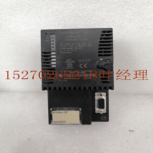
IS200TVBAH2ACC MRP646218工控备件模块,控制器模块
2000 GFK-0898F IC693ALG220 Alog输入模块现场接线信息下图提供了将现场接线连接到4-Alog电压输入模块的信息。4-Alog电压输入模块的现场接线如果电压源浮动到限制模式电压,则电压源的(-)侧也可以连接到COM端子。COM连接提供对模块中的模拟的访问。GND连接提供对基板(机架接地)的访问。有关接线和屏蔽接地连接的详细信息,请参阅第2章。Alog输入模块10 GFK-0898F第10章–Alog输入模件10-5 Alog电流输入-4 IC693ALG221 Series 90-30可编程逻辑控制器的4-Alog电流输出模块提供四个输入,每个输入都能够将模拟输入信号转换为数字信号,以供您的应用需要使用。该模块提供两个输入范围。默认范围是对用户数据进行缩放,使4对应于计数0,20对应于计数32000,每1000个计数代表0.5。当跳线添加到I/O端子板时,将输入范围更改为用户数据缩放,以使0对应于计数0,20对应于计数32000,每800个计数代表0.5。模块提供了两个范围跳线;一个是一号和二号,另一个是三号和四号。每四秒的转换速度为半毫秒。这为任何提供了两毫秒的更新速率。在任一范围内,转换后的sigl的分辨率为12位biry(4096分之一)。%AI寄存器中的用户数据处于16位2的补码状态。来自A/D转换器的12位在%AI数据字中的位置如下所示。电流输入和A/D转换器数据之间的关系如图3-14和3-15所示。X D11 D10 D9 D8 D7 D6 D5 D4 D3 D2 D1 D0 X X MSB LSB X=t适用于本讨论。4 A/D位(分)电流范围4647 0 20 0 4000图10-5。A/D位与电流输入如果电流源反向输入,或小于电流范围的低端,则模块将产生与电流范围低端相对应的数据字(0000H,%AI)。如果输入的输入超出范围(即大于20),A/D转换器将达到满量程(对应于%AI中的7FF8H)。输入比例如下图所示。电流范围a44654 0 20 0 4000 A/D位(小数)10 10-6系列90-30 PLC I/O模块规格–2000 GFK-0898F 4%AI(小数)电流范围A4455 0 20 0 32000图10-6。模块的Alog电流输入输入保护的缩放足以保证在高达200V模式下以降低的性能运行。该模块通过使用光学隔离在现场布线和背板之间提供外部产生的电隔离。为了最大限度地减少电容负载和噪声,模块的所有现场连接应使用良好等级的绞合屏蔽仪表电缆。屏蔽可以连接到COM或GND。COM连接提供对模块中的模拟的访问。GND连接提供对基板(机架接地)的访问。当模块电源工作时,面板顶部的LED亮起。模块的输入电源为PLC电源提供的隔离+24电源。该电压通过逆变器/调节器传输,为模块提供工作电压。该模块还消耗PLC电源+5的电力来驱动隔离系统。该模块可以安装在Series 90-30 PLC系统中5或10插槽基板的任何I/O插槽中。
2000 GFK-0898F IC693ALG220 Alog Input Module Field Wiring Infortion The following figure provides infortion for connecting field wiring to the 4- Alog Voltage Input module. Field Wiring for 4- Alog Voltage Input Module te The (–) side of the voltage source can also be tied to the COM termil if the source is floating to limit -mode voltages. The COM connection provides access to the of the alog ry in the module. The GND connection provides access to the baseplate (frame ground). Please refer to Chapter 2 for wiring and shield ground connection details. Alog Input Modules 10 GFK-0898F Chapter 10 – Alog Input Modules 10-5 Alog Current Input - 4 IC693ALG221 The 4- Alog Current Input module for the Series 90-30 Programble Logic Controller provides four input s, each capable of converting an alog input sigl to a digital sigl for use as required by your application. This module provides two input ranges. The default range is with user data scaled so that 4 corresponds to a count of 0 and 20 corresponds to a count of 32000 with each 1000 counts representing 0.5 . When a jumper is added to the I/O termil board, the input range is changed to with user data scaled so that 0 corresponds to a count of 0 and 20 corresponds to a count of 32000 with each 800 counts representing 0.5 . Two range jumpers are provided with the module; one for s one and two, and the other for s three and four. Conversion speed for each of the four s is one-half millisecond. This provides an update rate of two milliseconds for any . Resolution of the converted sigl is 12 bits biry (1 part in 4096) over either range. User data in the %AI registers is in 16-bit 2’s complement fort. The placement of the 12 bits from the A/D converter in the %AI data word is shown below. The relationship between the current input and the data from the A/D converter is shown in Figures 3-14 and 3-15. X D11 D10 D9 D8 D7 D6 D5 D4 D3 D2 D1 D0 X X X MSB LSB X=t applicable to this discussion. 4 A/D BITS (decil) CURRENT RANGE a44647 0 20 0 4000 Figure 10-5. A/D Bits vs. Current Input If the current source is reversed into the input, or is less than the low end of the current range, then the module will a data word corresponding to the low end of the current range (0000H in %AI). If an input that is out of range is entered (that is, it is greater than 20 ), the A/D converter will up to full scale (corresponding to 7FF8H in %AI). Input scaling is shown in the next figure. CURRENT RANGE a44654 0 20 0 4000 A/D BITS (decil) 10 10-6 Series 90-30 PLC I/O Module Specifications – 2000 GFK-0898F 4 %AI (decil) CURRENT RANGE a44655 0 20 0 32000 Figure 10-6. Scaling for Alog Current Input Input protection for the module is sufficient to guarantee operation with reduced perfornce with up to 200V -mode. The module provides electrical isolation of exterlly generated ise between field wiring and the backplane through the use of optical isolation. To minimize the capacitive loading and ise, all field connections to the module should be d using a good grade of twisted, shielded instrumentation cable. The shields can be connected to either COM or GND. The COM connection provides access to the of the alog ry in the module. The GND connection provides access to the baseplate (frame ground). An LED at the top of the faceplate is ON when the module’s power supply is operating. The in power source for the module is the isolated +24 power supplied by the PLC power supply. This voltage is routed through an inverter/regulator to provide the operating voltage for the module. This module also consumes power from the +5 of the PLC power supply to drive the isolation ry. This module can be installed in any I/O slot of a 5 or 10-slot baseplate in a Series 90-30 PLC system.
")
")
")
")

