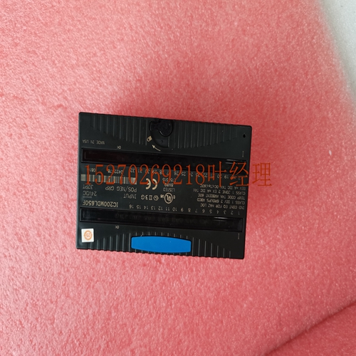
IS200VAICH1DAA DCS工控模块备件
90-30 PLC I/O模块规格–2000 GFK-0898F IC693MDL751模块现场接线信息下图提供了将用户提供的负载设备和电源连接到12/24伏直流正逻辑模块的接线信息。INTERL 0V COM典型a44847连接器端子现场接线+模块RY用户负载用户负载图7-38。现场布线-IC693MDL751 32点模块离散模块7 GFK-0898F第7章-离散模块7-43 5/24伏DC(TTL)负逻辑,32点IC693MDL 752系列90-30可编程逻辑控制器的5/24伏直流(TTL)负电逻辑模块提供32个离散s。这些模块排列成四个独立的八组(A1-A8、B1-B8、C1-C8和D1-D8);每个组都有自己的。s为负逻辑或下沉型s(即,点的ON状态导致激活低)。模块有两种操作模式。在TTL模式下,s可以在+5(±5%)范围内切换用户负载,并且能够每点吸收25的电流。在12/24V模式下,s可以在+12到-24(+20%,-15%)的范围内切换用户负载,并且每个点能够吸收0.5A的电流。用户I/O连接器上为每组提供了两个引脚。每个引脚的电流处理能力为3安培。连接时,建议断开两个引脚的连接;然而,这是高电流应用(3至4安培之间)的要求。每个组可用于满足特定应用的负载要求所需的操作模式。例如,组A可以驱动TTL负载,组B可以驱动12个负载,而组C和D可以保留用于驱动24个负载。然而,在混合TTL和电感型负载时,必须考虑电气噪声的影响,这一点很重要。为每个点提供了一个中间上拉电阻器。当点FET断开时,每个电阻器的功能是被动地向上拉用户正侧电源输入(对于TTL模式,通常为+5V),从而为TTL应用提供高逻辑电平。停止时,所有32秒强制关闭。向负载提供电流的电源必须由用户提供。该模块还从用户电源汲取最小量的电力,以向设备提供栅极驱动。场侧和逻辑侧之间的背板隔离由模块上的光耦合器提供。报告特殊故障或报警诊断。模块顶部的LED指示灯提供每个点的开/关状态。该模块配置为32点类型,使用32位离散%Q数据。该模块可安装在Series 90-30 PLC系统中5或10插槽基板的任何I/O插槽中。从用户的负载设备到安装在模块前部的两个le(针型)24针连接器(Fujitsu FCN-365P024-AU)的连接断开。安装在模块右侧的连接器(前视图)与A组和B组连接。模块左侧的连接器与C组和D组连接。现场设备直接接线法–该方法使用的电缆在模块端部有一个毛毡连接器,在另一端有剥线和镀锡。您可以购买一条预先订购的电缆,目录号为IC693CBL327和IC693CBL 328,或者,如果您的应用需要,您可以自己制作电缆。有关更多信息,请参阅本手册附录C中IC693CBL327/328数据表中的24针连接器建筑电缆。使用TBQC–Termil Block快速连接方法使用一条电缆,每端带有连接器。这些连接器从模块连接器连接到DIN导轨安装端子块上的连接器。TBQC组件在附录D.7 7-44 Series 90-30 PLC I/O模块规范–2000 GFK-0898F表7-23中讨论。IC693MDL752额定电压5和12至24伏DC,负逻辑(低有效)电压范围的技术规格
90-30 PLC I/O Module Specifications – 2000 GFK-0898F IC693MDL751 Module Field Wiring Infortion The following figure provides wiring infortion for connecting user supplied load devices and power source to the 12/24 volt DC positive logic module. INTERL 0V COM TYPICAL a44847 CONNECTOR TERMILS FIELD WIRING + MODULE RY USER LOAD USER LOAD USER LOAD Figure 7-38. Field Wiring - IC693MDL751 32 Point Module Discrete Modules 7 GFK-0898F Chapter 7 – Discrete Modules 7-43 5/24 Volt DC (TTL) Negative Logic , 32 Point IC693MDL752 The 5/24 volt DC (TTL) Negative Logic module for the Series 90-30 Programble Logic Controller provides 32 discrete s. The s are arranged in four isolated groups of eight (A1 - A8, B1 - B8, C1 - C8, and D1 - D8); each group has its own . The s are negative logic or sinking type s (i.e., the ON state for a point results in an active low ). The module has two modes of operation. In the TTL mode, the s can switch user loads across +5 (±5%) and are capable of sinking a current of 25 per point. In the 12/24V mode, the s can switch user loads over the range of +12 through –24 (+20%, –15%) and are capable of sinking a current of 0.5A per point. Two pins are provided on the user I/O connectors for each group . Each pin has a current handling capability of 3 amperes. It is recommended that connections are de to both pins when connecting the ; however, it is a requirement for high current applications (between 3 and 4 amperes). Each group can be used in the mode of operation needed to satisfy the load requirements for a particular application. For example, group A can drive TTL loads and group B can drive 12 loads, while group C and D can be reserved for driving 24 loads. It is important to te, however that the effects of electrical ise must be considered when mixing TTL and inductive-type loads. An interl pull-up resistor is provided for each point. The function of each resistor is to passively pull up the to the user positive side power input (typically +5V for TTL mode) when the point FET is OFF, thereby providing a high logic level for TTL applications. All 32 s are forced OFF when the is stopped. Power to provide current to the loads must be provided by the user. The module also draws a minimum amount of power from the user supply to provide gate drive to the devices. Backplane isolation between the field side and logic side is provided by opto-couplers on the module. special fault or alarm diagstics are reported. LED indicators at the top of the module provide the ON/OFF status of each point. This module is configured as a 32-point type and uses 32 bits of discrete %Q data. This module can be installed in any I/O slot of a 5 or 10-slot baseplate in a Series 90-30 PLC system. Connections to the s are de from the user’s load devices to two le (pin-type) 24-pin connectors (Fujitsu FCN-365P024-AU) mounted on the front of the module. The connector mounted on the right of the module (front view) interfaces with groups A and B. The connector on the left side of the module interfaces with groups C and D. Wiring to Field Devices Direct Method – This method uses cables that have a ting fele connector on the module end and stripped and tinned s on the other end. You can purchase a of pre-d cables, catalog numbers IC693CBL327 and IC693CBL328 or, if required for your application, build your own cables. Refer to Building Cables for 24-Pin Connectors in the IC693CBL327/328 data sheet in Appendix C of this nual for more infortion. Using a TBQC – The Termil Block Quick Connect method uses a of cables with connectors on each end. These connect from the module connectors to connectors on DIN–rail mounted termil blocks. The TBQC components are discussed in Appendix D. 7 7-44 Series 90-30 PLC I/O Module Specifications – 2000 GFK-0898F Table 7-23. Specifications for IC693MDL752 Rated Voltage 5, and 12 through 24 volts DC, negative logic (active low) Voltage Range


