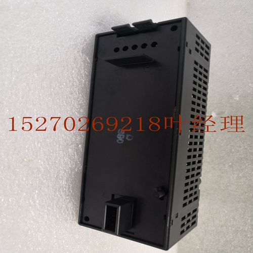
IS210AEDBH3ACC工控备件机器人模块
FIP同步驾驶室的SYNRO。它需要一个ting-su作为Mox#。在应用中不使用同步能力。接地Synro下面的接线片用于提供的接地。接地的另一端必须与和辅助接地的下英尺角上的安装螺栓连接。在顶部有两个D。上部用于,下部用于。CDCD绿色载波Decd Ds表示其各自的s上存在载波信号NN红色传输Ebd Ds表示在其各自的s上生成传输。FIP Remo扫描仪文档:FIP Remo扫描仪FIP总线控制器Q apr选件的ICAPU轴定位APM APM是一种易于使用的单轴ICAPU或双轴ICAPU控件。APM允许用户在一个集成系统中实现具有逻辑求解功能的高性能控制。APM可以配置为标准模式或跟随模式。当在标准模式下使用时,它将高性能控制与逻辑求解功能结合在一起。当用于从动模式时,它为连续从动应用提供了高性能的电子传动装置。通过在配置软件中配置设置参数,可以轻松设置所需模式。AXIS POS STAT OK CFG EN EN ONE AXIS B A C O M图。APM和APM作为一个集成的控制包。APM控制轴和指针,所有这些都控制驱动器和线路,同时自动在选项卡和APM之间传输数据。还提供了一种连接操作器界面的方法,该界面可以控制和监视系统操作。APM伺服系统的一个示例显示了所使用的硬件和软件,配置程序和操作系统如下所示。APM可以安装在任何CPU扩展或远程中。对于嵌入式CPU,您最多可以有三个APM。对于lar CPU或更高版本,您可以在一个系统中最多有八个APM,每个系统有三个APM。可以在APM中创建和存储多个程序,也可以使用编程器软件包在APM内存储。APM使用VersaPro软件版本进行配置和编程。或lar或Logic Developer。安装和硬件八月Q APM facepla前面板具有用于伺服连接的双针高密度。标签A包含Axis的连接。B轴APM包含通用连接。B轴APM具有轴连接和通用连接。布线更容易,驱动器和线路的高密度通常由一个短的驾驶室连接。CPU DRIVE INE ENCODER DRIVE INE编码器配置软件编程软件APM图。APM伺服系统APM驾驶室示例这些驾驶室由一个销a驾驶室和一个销D型块组成。4月记录了电缆。Ailab驾驶室为:ICCBL英尺mers ICCBL
SYNRO for a FIP synronization cab. It requires a ting su as Mox #. The synronization capability is t used in a application. ground The lug below the Synro is used for the ground provided. The other end of the ground must be connecd the mounting bolt on the lower ft corner of the and assis ground. Ds There are two s of Ds at the p of the . The upper is for and the lower is for . CDCD The green Carrier Decd Ds indica the presence of a carrierdect sigl on their respective s. NN The red Transmission Ebd Ds indica the is generating transmissions on their respective s. FIP Remo Scanner Documentation: FIP Remo Scanner FIP Bus Controlr Q apr Option s ICAPU Axis Positioning APM The APM is an easyuse inlligent fully oneaxis ICAPU or twoaxis ICAPU control for the . The APM allows a user bine highperfornce control with logic solving functions in one ingrad sysm. The APM can be configured opera in either Standard mode or Follower mode. When used in Standard mode it bines highperfornce control with logic solving functions in one ingrad sysm. When used in Follower mode it provides highperfornce ectronic gearing for continuous srslave applications. The desired mode is easily secd by configuring a setup paramer in the configuration software. AXIS POS STAT OK CFG EN EN ONE AXIS B A C O M M Figure . APM The and APM opera gether as one ingrad control package. The APM controls axis and hands all direct the drive and ine whi the autically transfers data between tabs and the APM. The also provides a means for connecting Operar Inrfaces whi can control and monir sysm operation. An examp of an APM servo sysm showing the hardware and software used configure program and opera the sysm is shown below. The APM can be instald in any CPU expansion or remo . For embedded CPUs or you y have up three APM s. For a lar CPU or higher you y have up eight APM s in one sysm with a of three APM s per . Multip programs y be cread and sred in the APM of y be sred in the APM with the Programmer software package. The APM is configured and programmed with VersaPro software Version . or lar or Logic Developer. Installation and Hardware August Q The APM facepla front panel has two pin highdensity s for servo connections. The labed A contains connections for Axis . B for a axis APM contains general purpose connections. B for a axis APM has connections for Axis as well general purpose connections. ke wiring easier the drive and ine ea highdensity is typically connecd by a short cab a block. CPU DRIVE INE ENCODER DRIVE INE ENCODER Configuration Software Programming Software APM Figure . Examp of APM Servo Sysm APM Cabs These cabs consists of a pin a cab and a pin Dtype block . Cabs are documend in apr . Ailab cabs are: ICCBL feet mers ICCBL


