


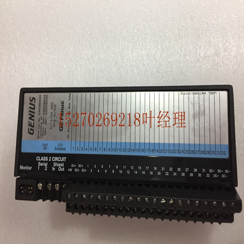
IS215ISBBH1A ABB卡件,工业卡件
.A X.输入功率程序控制器图。输入电源ICPWR Q apr电源选项卡。ICPWR电源规范额定Rad电压输入电压范围满载时的输入功率浪涌电流A峰值ms总三个s电压。标称隔离保护极限过电压:过电流;保持时间:ms最小标准参考数据表B或lar版本的产品标准和一般规范。计算ICPWR的输入功率要求下图是典型的电源效率曲线。电源效率测定的基本程序如下图所示。平均输入功率TAL功率W图。ICPWR电源的典型效率曲线:满载时无启动浪涌,单位为毫秒。ICPWR电源的安装和硬件8月Q输入功率电流计算从4月为个人列出的典型规范中减去总负载。使用图表dermine平均输入功率。将输入功率除以工作电源电压,以确定输入电流要求。使用最低输入电压确定输入电流。考虑启动浪涌电流要求。允许使用精氨酸。Q apr电源ICPWR大容量电源输入直流输入大容量电源ICPW是一种专为额定输入设计的宽功率范围电源。对于需要比标准电源更大的+V电流容量的应用,该电源允许从+V消耗所有电流。它将接受来自的输入电压范围。尽管它能够在输入电压低到最低的情况下将所有s保持在规格范围内,但它不会从小于的初始输入电压开始。此电源提供以下功能:+。+继电器电源,该电源为继电器s提供电源。某些s内部使用的隔离+也可用于为输入s提供外部电源。该电源的每个负载容量显示在下表中。ICPWR电源容量目录号负载容量输入容量电压功率ICPWR++隔离开关+所有组合的继电器总数不能超过。程序控制系统状态指示器+PWR正常运行电池B A T E R Y锂备用电池S RS PATIB串行端口连接直流电源内部电源需要ICPWR电源。A X高容量+输入功率图。输入大容量电源ICPWR安装和硬件8月Q选项卡。ICPWR电源规范额定Rad电压输入电压范围满载时的启动运行输入功率浪涌电流功率:总计三个s电压。标称Isolad。普氏极限过电压:过电流;A滞留时间:ms最小标准参考数据表B或lar版本的产品标准和一般规范。取决于安装和电源阻抗。环境温度高于C F时的减额。温度较高时的电流减额图。温度高于C F电流环境温度C Q apr电源的电流降额计算ICPWR的输入功率要求使用以下程序确定大容量电源的输入功率需求:从本月底列出的单个电源的典型规格中减去总功率负载。将功率乘以。确定输入功率值。将输入功率值除以工作电源电压dermine输入电流要求使用最低输入电压dermine输入电流允许启动浪涌电流要求允许漏电流现场接线连接直流不间断电源直流电源连接直流电源的+和s连接带+应与p螺钉连接,第二个螺钉应从p向下计数。接地连接连接第三个螺钉。这条连接线被标记在这些电源的前面。Isolad电源连接电源条的底部两个提供Isolad+伏直流电连接,可用于在电源的功率限制范围内为外部提供电源。警告:如果隔离电源过载或短路,逻辑控制器将停止工作。
. A X. Input Power Program Controller Diagram. Input Power ICPWR Q apr Power tab. ICPWR power supply specification Rated Rad voltage Input voltage range Input power Surge current A peak ms at full load Total three s voltages. Nominal isolation protection limit over-voltage: over-current; Retention time: ms minimum standard refers to product standard and general specification of data sheet B or lar version. The following figure is a typical power efficiency curve for calculating the input power requirements of ICPWR. The basic procedure for power efficiency measurement is shown in the figure below. Average input power TAL power W diagram. Typical efficiency curve of ICPWR power supply: no startup surge under full load, in milliseconds. Installation of ICPWR power supply and calculation of Q input power current in August of hardware subtract the total load from the typical specifications listed for individuals in April. Use the graph dermine to average the input power. Divide the input power by the operating supply voltage to determine the input current requirements. Use the lowest input voltage to determine the input current. Consider starting surge current requirements. Arginine is allowed. Q apr power supply ICPWR large capacity power input DC input large capacity power supply ICPW is a wide power range power supply designed for rated input. For applications requiring a greater+V current capacity than the standard power supply, the power supply allows all current to be drawn from the+V. It will accept the input voltage range from. Although it can keep all s within the specification range when the input voltage is low to the minimum, it will not start from the initial input voltage less than. This power supply provides the following functions:++ Relay power supply, which provides power for relay s. The isolation+used internally by some s can also be used to provide external power to the input s. Each load capacity of the power supply is shown in the following table. ICPWR power supply capacity catalog number load capacity input capacity voltage power ICPWR++disconnector+total number of all combined relays cannot exceed. Program control system status indicator+PWR normal operation battery B A T E R Y lithium backup battery S RS PATIB serial port connection DC power supply Internal power supply requires ICPWR power supply. A X High Capacity+Input Power Graph. Enter the high-capacity power ICPWR installation and hardware August Q tab. ICPWR power supply specification Rated Rad voltage Input voltage range Starting operation input power at full load Surge current power: three s voltages in total. Nominal Isolad. Proctor limit overvoltage: overcurrent; A Retention time: ms minimum standard refers to the product standard and general specification of data sheet B or lar version. Depends on installation and power impedance. Derate for ambient temperatures above C F. Current derating diagram at high temperature. Current derating for power supplies with temperatures above C F current ambient temperature C Q apr Input power requirements for calculating ICPWR Use the following procedure to determine the input power requirements for large capacity power supplies: Subtract the total power load from the typical specifications for individual power supplies listed at the end of this month. Multiply the power by. Determine the input power value. Divide the input power value by the working power supply voltage dermine input current. The minimum input voltage dermine input current is required to allow the starting surge current. It is required to allow the leakage current field wiring to connect the DC uninterruptible power supply. The+and s connecting bands of the DC power supply and the DC power supply should be connected with the p screw. The second screw should be counted from p down. The ground connection connects the third screw. This cable is marked on the front of these power supplies. Isolade power connection The bottom two of the power strip provide Isolade+V DC connection, which can be used to provide external power within the power limit of the power supply. Warning: If the isolated power supply is overloaded or short circuited, the logic controller will stop working.
")
")
")

