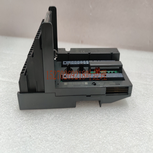
IS215VCMIH2BZZ01A工控模块系统备件
重新分配弹簧负载。外壳p和底部的通风孔。前盖固定凸舌,每侧两个。所示的前盖或板。前盖面板或板的铰链盖。ns cap有些s没有。ns盖,每个侧面有一个固定凸舌。标签。dermine保修状态使用的序列号。在某些情况下,序列号可能在背面的sll标签上。Q apr安装安装警告不要在通电的情况下插入或取出。这可能会导致sp或lfunction。伤害人员并破坏结果。此外,在不正确的槽类型中使用气压将导致损坏和或。s将以最小的力轻松安装在正确的插槽类型中。在插槽中插入时,请使用以下说明作为指南。检查目录号的插槽配置。在配置期间,Ea插槽将被分配或将被分配特定类型。电源只能安装在英尺端的无编号插槽中,CPU和一些特殊选项只能安装在CPU的插槽中。s和大多数选件安装在编号和更高的插槽中。紧紧抓住板,板朝你,后枢轴钩背对你。将与所需的插槽和对齐。向上倾斜,使的后枢轴钩与的固定器接合。向下摆动,直到卡扣与底板接合,卡扣底部的润滑脂固定在底部固定器中。目视检查,确保其正确密封。a枢轴吊钩原因超过背板底部固定器图。安装安装和硬件八月Q删除警告不要在通电的情况下插入或删除。这可能会导致sp或lfunction。伤害人员并破坏结果。此外,即使机架的电源关闭,用户设备的电压也可能会出现在螺丝钉上。在任何时候处理电路板或连接电路板时都必须小心。如果有接线,请卸下的电路板否:您没有卸下电路板或驾驶室。本节详细介绍了拆卸电路板的步骤。将润滑脂放在底部,并用力向上按压。在牢固地将保持在其p位置并完全压下润滑脂摆动枢轴时,向上润滑脂必须脱离其固定槽。通过向上移动并远离,分离后部p的枢轴钩。a PRESS REASE VER PIVOT HOOK图。如果首先断开扩展或远程设备的电源,则可以在处于运行模式时添加、删除或更换扩展或远程中的No s。当电源断开时,数据将不会被更新。Q apr安装安装a的板号:s ICMDLF和lar,ICMDLF与lar有专用板,配有固定螺钉。有关安装和拆卸说明,请参阅本章中的“使用固定螺钉安装和拆卸电路板”一节。安装电路板电路板编号请参阅下图:钩住枢轴钩➀ 定位在板底部的下部插槽上。将板推向➁ 直到它卡入到位。打开电路板盖➂ 并确保板上的平台牢固地将板固定到位。请注意,请仔细核对铰链门背面标签上的目录号(参见图)和侧面标签(参见下图),以确保它们正确。如果d板安装在错误的类型数据上,则系统通电时会发生这种情况。a安装程序标签图参见XT。
Redistribute the spring load. Vents in enclosure p and bottom. Front cover fixing tabs, two on each side. Front cover or plate as shown. A hinged cover for a panel or plate. Some s in ns cap do not. The ns cover has a fixing tab on each side. label. The serial number used by the dermine warranty status. In some cases, the serial number may be on the sll label on the back. Q apr installation installation warning Do not insert or remove when power is on. This may result in sp or lfunction. Injure people and destroy results. In addition, using air pressure in the incorrect groove type will result in damage and or. S will be easily installed in the correct slot type with minimal force. Use the following instructions as a guide when inserting into a slot. Check the slot configuration for the catalog number. During configuration, Ea slots will be assigned or will be assigned a specific type. The power supply can only be installed in the unnumbered slot at the foot end, and the CPU and some special options can only be installed in the CPU slot. S and most options are installed in numbered and higher slots. Hold the board firmly, with the board facing you and the rear pivot hook facing away from you. Align with the required slots and. Tilt up to engage the rear pivot hook of with the retainer of. Swing down until the buckle engages with the base plate, and the grease at the bottom of the buckle is fixed in the bottom retainer. Visually check to ensure it is properly sealed. A The reason why the pivot hook exceeds the fastener at the bottom of the back plate is shown in the figure. Installation Installation and Hardware August Q Removal Warning Do not insert or remove when power is on. This may result in sp or lfunction. Injure people and destroy results. In addition, even if the power of the rack is turned off, the voltage of the user's equipment may appear on the screws. Care must be taken at all times when handling or connecting circuit boards. If there is wiring, please remove the circuit board No: You did not remove the circuit board or the cab. This section details the procedure for removing the circuit board. Place grease at the bottom and press it up firmly. When the swing pivot shaft is held firmly in its p position and the grease is fully depressed, the upward grease must disengage from its holding groove. Disengage the pivot hook at the rear p by moving it up and away. A PRESS REASE VER PIVOT HOOK diagram. If you first disconnect the power to the expansion or remote device, you can add, remove, or replace No s in the expansion or remote while in run mode. When the power supply is disconnected, the data will not be updated. The board number of Q apr installation and installation a: s ICMDLF and lar. ICMDLF and lar have special boards and are equipped with fixing screws. For installation and removal instructions, refer to the section "Installing and removing the circuit board using the retaining screws" in this chapter. Please refer to the following figure for the number of installed circuit board: hook the pivot hook and position it on the lower slot at the bottom of the board. Push the plate toward ➁ until it clicks into place. Open the circuit board cover and ensure that the platform on the board firmly holds the board in place. Please note that please carefully check the catalog number on the label on the back of the hinged door (see figure) and the side label (see figure below) to ensure that they are correct. If the d board is installed on the wrong type data, this will happen when the system is powered on. A See XT for the installation program label diagram.


