


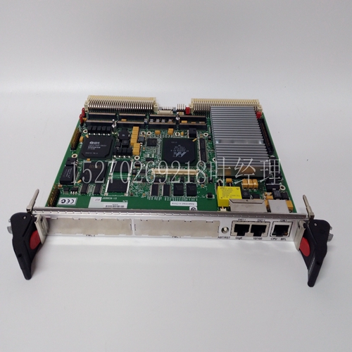
MVME167P-36SE模拟量输入模块
2.验证应用中的轴向和径向轴负载不超过第15页电机负载力额定值中列出的值。3.将电机与电缆连接放置在电机下方。有关正确电机和电缆定位的视觉参考,请参阅第4页的拆卸轴盖。4.正确安装和对齐电机:Bulletin MPL电机包括一个安装导向器,用于在机器上对齐电机。当轴键与连接器对齐时,2000线编码器上出现索引脉冲。确保皮带负载在电机限制范围内,并且所有皮带和滑轮正确对齐。遵循制造商对齿轮箱、滑轮或其他电机附件的建议。注意:如果在安装联轴器和皮带轮期间对轴施加剧烈冲击,可能会损坏电机轴承和反馈装置。在安装或拆卸过程中,不要用工具敲击轴、联轴器或皮带轮。注意:电机的外表面在运行过程中可能会达到125°C(275°F)的高温。采取预防措施,防止意外接触热表面。选择电机配合连接和电缆时,应考虑电机表面温度。MP系列75 mm或更小框架尺寸的低惯量无刷伺服电机11罗克韦尔自动化出版物MP-IN006D-EN-P-2015年1月连接电机电缆安装电机后,按照以下步骤连接反馈和电源/制动电缆。1.如果使用螺纹DIN(M4)电缆插头,请安装O形圈。接头上的O形圈是实现最大环境等级所必需的。2.如果使用SpeedTec DIN(M7)电缆插头,请勿安装O形圈。3.在电缆中形成滴水环(见第5页)。
注意:在将电缆连接或断开电机之前,必须关闭伺服驱动电源,如果电缆在电机端断开,也必须关闭。如果在伺服驱动器通电时连接或断开反馈电缆、电源电缆或制动电缆,可能会发生电弧或意外运动。注意:确保电缆已安装并受到约束,以防止电缆连接器处的不均匀张力或弯曲。在整个电缆敷设过程中,每隔3米(10英尺)提供支撑。当电缆弯曲或电缆压盖处的电线分离时,电缆连接器处的横向力过大且不均匀会导致连接器的环境密封打开和关闭。SpeedTec ready DIN电机连接器不要在SpeedTec就绪DIN电机连接器上安装O形圈螺纹DIN(M4)电缆插头2090 XXNxMF Sxx标准反馈和电源电缆2090-CxxM4DF-xxAFxx连续挠性反馈、电源和电源/制动电缆使用螺纹DIN(M3)电缆插头时,在SpeedTech就绪DIN电机接头上安装O型圈。确认O形圈未损坏、未扭曲,并位于接头后部附近的凹槽中。电缆插头预留槽使用SpeedTec DIN(M7)电缆插头时,请勿在SpeedTec就绪DIN电机连接器上安装O形圈。SpeedTec DIN(M7)电缆插头2090-CFBM7Dx-xxAxxx标准和连续柔性反馈电缆2090-CPxM7DF-xxAxxx标准以及连续柔性电源/制动电缆SpeedTec就绪DIN电机连接器12 MP系列低惯量无刷伺服电机,75 mm或更小框架尺寸罗克韦尔自动化出版物MP-IN006D-EN-P-2015年1月4日。小心地将反馈或电源/制动电缆插头(如图所示)上的平面与电机接头上的平面对齐。5.用手拧紧插头上的套环,使其完全固定在连接器上:螺纹DIN(M4)电缆插头需要旋转五到六圈。SpeedTec DIN(M7)电缆插头需要大约四分之一转。
2. Verify that the axial and radial shaft loads in the application do not exceed the values listed in Motor Load Force Ratings on page 15. 3. Place the motor and cable connection under the motor. For a visual reference to correct motor and cable positioning, refer to Removing the Shaft Cover on page 4. 4. Install and align the motor correctly: The Bulletin MPL motor includes a mounting guide for aligning the motor on the machine. When the axis key is aligned with the connector, the index pulse appears on the 2000 line encoder. Make sure that the belt load is within the limits of the motor and that all belts and pulleys are correctly aligned. Follow the manufacturer's recommendations for gear boxes, pulleys, or other motor accessories. Note: If the shaft is severely impacted during the installation of the coupling and pulley, the motor bearing and feedback device may be damaged. Do not knock the shaft, coupling or pulley with tools during installation or removal. Note: The outer surface of the motor may reach a high temperature of 125 ° C (275 ° F) during operation. Take precautions to prevent accidental contact with hot surfaces. The motor surface temperature shall be considered when selecting the motor mating connection and cable. MP series low inertia brushless servo motor with 75 mm or smaller frame size 11 Rockwell Automation publication MP-IN006D-EN-P-2015 Connect the motor cable In January 2015, after installing the motor, connect the feedback and power/brake cables according to the following steps. 1. If threaded DIN (M4) cable plug is used, please install O-ring. The O-ring on the connector is necessary to achieve the maximum environmental rating. 2. If SpeedTec DIN (M7) cable plug is used, do not install O-ring. 3. Form a drip loop in the cable (see page 5).
Note: Before connecting or disconnecting the cable from the motor, the servo drive power must be turned off. If the cable is disconnected at the motor end, it must also be turned off. If the feedback cable, power cable or brake cable is connected or disconnected when the servo drive is powered on, arcing or unexpected movement may occur. NOTE: Make sure the cable is installed and restrained to prevent uneven tension or bending at the cable connector. Support shall be provided every 3 meters (10 feet) throughout the cable laying process. When the cable is bent or the wires at the cable gland are separated, excessive and uneven lateral force at the cable connector will cause the environmental seal of the connector to open and close. SpeedTec ready DIN motor connector Do not install O-ring threaded DIN (M4) cable plug 2090 XXNxMF Sxx standard feedback and power cable 2090-CxxM4DF xxAFxx continuous flexible feedback, power and power/brake cables. When using threaded DIN (M3) cable plug, install O-ring on SpeedTech ready DIN motor connector. Verify that the O-ring is not damaged, twisted, and located in the groove near the rear of the connector. When SpeedTec DIN (M7) cable plugs are used in the cable plug preparation slot, do not install O-rings on the SpeedTec ready DIN motor connector. SpeedTec DIN (M7) cable plug 2090-CFBM7Dx xxAxxx standard and continuous flexible feedback cable 2090-CPxM7DF xxAxxx standard and continuous flexible power/brake cable SpeedTec ready DIN motor connector 12 MP series low inertia brushless servo motor, Rockwell automation publication MP-IN006D-EN-P-2015, January 4, 2015. Carefully align the plane on the feedback or power/brake cable plug (as shown in the figure) with the plane on the motor connector. 5. Tighten the ferrule on the plug by hand to make it completely fixed on the connector: the threaded DIN (M4) cable plug needs to be rotated five to six turns. SpeedTec DIN (M7) cable plugs require about a quarter turn.
")
")
")
")
")
")

