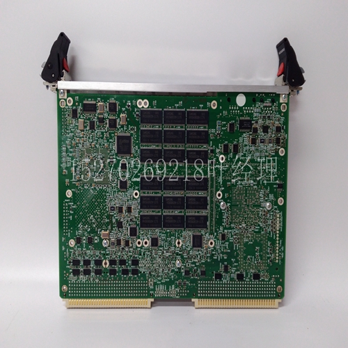
MVME167PA-24SE DCS模块卡件
工厂提供的现场修改验证驱动器上的电源电缆接地夹是否接触所有(三个)电缆屏蔽。BR+BR-+-直流电源客户提供的部件制动继电器二极管或MOV电弧抑制器MP系列低惯量无刷伺服电机,具有75 mm或更小的框架尺寸9罗克韦尔自动化出版物MP-IN006D-EN-P-2015年1月安装电机MP系列电机包括一个安装导杆,用于在机器上对齐电机。优选的紧固件为不锈钢。安装必须符合所有当地法规,并使用促进安全和电磁兼容性的设备和安装实践。更改连接器方向您可以将连接器外壳旋转180°。这使您可以将连接器调整到最佳位置,以保护连接免受可能的环境污染,同时提供电缆接入。圆形DIN连接器外壳可沿任一方向旋转180°。按照以下步骤旋转DIN连接器。1.在反馈或电源/制动接头上安装并完全固定配合电缆。2.用手抓住配合的连接器和电缆插头,并将其缓慢旋转至电机外部。3.对另一个接头重复这些步骤。注意:如果通电,未安装的电机、断开的机械联轴器、松脱的轴键和断开的电缆都是危险的。锁定并标记拆卸的设备(限制电源)。
向电机通电前,取下轴键和其他可能从轴上抛出的机械联轴器。注意:确保电缆已安装并受到约束,以防止电缆连接处的不均匀张力或弯曲。当电缆弯曲时,电缆上过大且不均匀的横向力会抑制环境密封。注意:连接器设计为在电机安装期间旋转到固定位置,并保持在该位置,无需进一步调整。不要多次旋转连接器,也不要使用工具或过度用力旋转连接器。过度旋转或用力会损坏连接器密封,降低电机的国际防护(IP)等级,如第20页规范所述。注意:仅对电机连接器和电缆插头施加力。不要对从电缆插头伸出的电缆施加力。不要使用工具(例如钳子和虎钳)旋转连接器。10 MP系列75 mm或更小框架尺寸的低惯量无刷伺服电机罗克韦尔自动化出版物MP-IN006D-EN-P-2015年1月安装电机按照以下步骤安装电机。1.为电机提供足够的间隙、散热质量和气流,使其保持在0…40°C(32…104°F)的工作温度范围内。除非强制冷却空气穿过电机,否则不要封闭电机,并使其他发热设备远离电机。散热器要求列于第20页规范的脚注中。
Factory supplied field modifications verify that the power cable ground clip on the drive contacts all (three) cable shields. BR+BR -+- DC power Customer supplied components Brake relay diode or MOV arc suppressor MP series low inertia brushless servo motor with 75 mm or smaller frame size 9 Rockwell Automation publication MP-IN006D-EN-P-2015 January installation motor MP series motors include a mounting guide for aligning the motor on the machine. The preferred fastener is stainless steel. The installation must comply with all local regulations and use equipment and installation practices that promote safety and electromagnetic compatibility. Changing the connector orientation allows you to rotate the connector housing 180 °. This allows you to adjust the connector to the optimal position to protect the connection from possible environmental pollution while providing cable access. The circular DIN connector housing can be rotated 180 ° in either direction. Follow the steps below to rotate the DIN connector. 1. Install and completely fix the matching cable on the feedback or power/brake connector. 2. Grasp the mating connector and cable plug by hand and slowly rotate them to the outside of the motor. 3. Repeat these steps for the other connector. Note: If the power is on, the unmounted motor, the disconnected mechanical coupling, the loose shaft key and the disconnected cable are dangerous. Lock and mark the removed equipment (restricted power supply).
Before energizing the motor, remove the shaft key and other mechanical couplings that may be thrown from the shaft. NOTE: Make sure that the cable is installed and restrained to prevent uneven tension or bending at the cable connections. When the cable is bent, excessive and uneven lateral forces on the cable will inhibit environmental sealing. Note: The connector is designed to rotate to a fixed position during motor installation and remain in that position without further adjustment. Do not rotate the connector more than once, nor use tools or excessive force to rotate the connector. Excessive rotation or force can damage the connector seal and reduce the international protection (IP) rating of the motor, as described in the specifications on page 20. Note: Apply force to motor connector and cable plug only. Do not apply force to the cable protruding from the cable plug. Do not use tools such as pliers and vises to rotate the connector. 10 MP series low inertia brushless servo motor with 75 mm or smaller frame size Rockwell Automation publication MP-IN006D-EN-P-2015 January installation of motor Install the motor according to the following steps. 1. Provide sufficient clearance, heat dissipation quality and airflow for the motor to keep it within the operating temperature range of 0... 40 ° C (32... 104 ° F). Do not close the motor and keep other heating equipment away from the motor unless forced cooling air passes through the motor. The radiator requirements are listed in the footnote to the specification on page 20.

