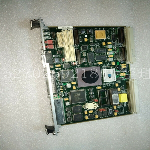
MVME172-343A模块控制器
在这些应用中,垫子系统检测操作员的存在,以防止操作员在外壳内时重置周界防护系统并重新启动机器。图13注:固定防护装置应符合EN 953、EN 294和EN 811的要求。合适的周界防护系统应为固定防护装置,该防护装置配有检修门,并配有带条件防护装置解锁的联锁开关(见EN 1088)。诸如安全光幕的跳闸装置也可适用于某些应用。需要注意的是,光幕的位置必须根据EN 999进行计算。在这些应用中使用垫子系统时,操作员可接近的整个封闭地板区域应覆盖传感器垫子。危险压力敏感垫固定防护联锁门(带锁)19 5.5固定防护装置固定防护装置的设计应确保除通过垫系统外,无法进入危险区域。防护装置的构造和定位应符合EN 953、EN 294和EN 811的要求。5.6良好的安装设计和防止旁路的措施如果不站在垫子上,就不可能到达危险区域。必须防止从不涉及站在垫子上的位置进入危险区域。这通常需要额外的角板以及管道和线槽的小心定位。这方面的良好实践如图14所示。图14 1。固定防护装置防止进入危险区域,从而使防护装置和传感器之间无法进入。2.倾斜盖板防止操作员站在机器底板上避开感应区域。3.传感器边缘的跳闸危险通过入口处的斜坡减少。
斜坡还可以保护连接电缆。可选的周界修剪是渐变截面。4.电缆槽安装在固定防护装置的外部。这可防止其被误用为进入危险区域。5.复位按钮位于保护良好的位置,可完全看到机器。6.垫安装正确。5.7电气接口系统提供的保护取决于系统和机器之间的正确接口。系统的安全输出触点布置为两个独立的无电压N/O触点对。端子位置在第6.2节中给出,额定值在第4.1 2 6 4 5 1 3 20节中给出。根据EN 954-1,控制单元符合第3类。与其他安全垫和地板一样,传感器垫的第3类性能无法在严重机械损坏或长期退化导致的故障中实现。根据EN 954-1,传感器垫符合第1类。由互连传感器垫和控制单元组成的系统符合EN 954-1第3类的要求。垫系统可用作唯一的保护措施或与其他措施或装置(如安全光幕、工作系统)结合使用。如果协调的欧洲“C”标准适用于机器类型,它将包含机器安全相关控制系统的要求和指南。EN954-1也提供了指导。重要的是,应根据EN 954-1的适当类别提供针对可预见故障的充分保护,因此,建议在所有高风险应用中使用具有复制和监控最终开关元件(接触器)的双通道配置。图15、16、17和18给出了垫系统的互连示例。21图15显示了单接触器(单通道)、440F-4000P和440F-C4000S应用的示例连接图。电路状态-电源打开-传感器垫上不存在-复位按钮已操作(如果处于手动复位模式)-机器启动电路已启用。
In these applications, the mat subsystem detects the presence of the operator to prevent the operator from resetting the perimeter protection system and restarting the machine while inside the enclosure. Note to Figure 13: Fixed protective devices shall comply with the requirements of EN 953, EN 294 and EN 811. A suitable perimeter protection system shall be a fixed guard with an access door and an interlock switch with conditional guard release (see EN 1088). Tripping devices such as safety light curtains may also be suitable for certain applications. It should be noted that the position of the light curtain must be calculated according to EN 999. When using the mat subsystem in these applications, the entire enclosed floor area accessible to the operator shall be covered with the sensor mat. Dangerous pressure sensitive pad fixed protective interlocking door (with lock) 19 5.5 Fixed protective device Fixed protective device shall be designed to ensure that the hazardous area cannot be accessed except through the pad system. The construction and positioning of protective devices shall comply with the requirements of EN 953, EN 294 and EN 811. 5.6 If good installation design and bypass prevention measures do not stand on the mat, it is impossible to reach the hazardous area. It must be prevented from entering the hazardous area from a position that does not involve standing on the mat. This usually requires additional gussets and careful positioning of pipes and trunking. Good practices in this area are shown in Figure 14. Figure 14 1. Secure the guards to prevent entry into the hazardous area so that there is no access between the guards and the sensors. 2. Tilt the cover plate to prevent the operator from standing on the machine floor to avoid the sensing area. 3. Trip hazard at the edge of the sensor is reduced by the ramp at the entrance.
The slope also protects the connecting cable. The optional perimeter trim is a gradient section. 4. The cable tray shall be installed outside the fixed protective device. This prevents it from being misused to enter hazardous areas. 5. The reset button is located in a well protected position, and the machine can be completely seen. 6. The gasket is installed correctly. 5.7 The protection provided by the electrical interface system depends on the correct interface between the system and the machine. The safe output contacts of the system are arranged as two independent voltage free N/O contact pairs. Terminal locations are given in Section 6.2 and ratings are given in Section 4.1 2 6 4 5 1 3 20. According to EN 954-1, the control unit complies with category 3. As with other safety pads and floors, the Class 3 performance of sensor pads cannot be achieved in the case of failures caused by severe mechanical damage or long-term degradation. According to EN 954-1, the sensor pads comply with category 1. The system consisting of interconnected sensor pads and control units complies with the requirements of EN 954-1, class 3. The cushion system can be used as the only protective measure or in combination with other measures or devices (such as safety light curtain and working system). If the harmonized European "C" standard applies to machine types, it will contain requirements and guidelines for machine safety related control systems. EN954-1 also provides guidance. It is important that adequate protection against foreseeable faults should be provided in accordance with the appropriate categories of EN 954-1, therefore it is recommended that a dual channel configuration with duplicated and monitored final switching elements (contactors) be used in all high-risk applications. Figures 15, 16, 17, and 18 show interconnection examples of the mat system. 21 Figure 15 shows an example connection diagram for single contactor (single channel), 440F-4000P and 440F-C4000S applications. Circuit status - power on - not present on sensor pad - reset button operated (if in manual reset mode) - machine start circuit enabled.


