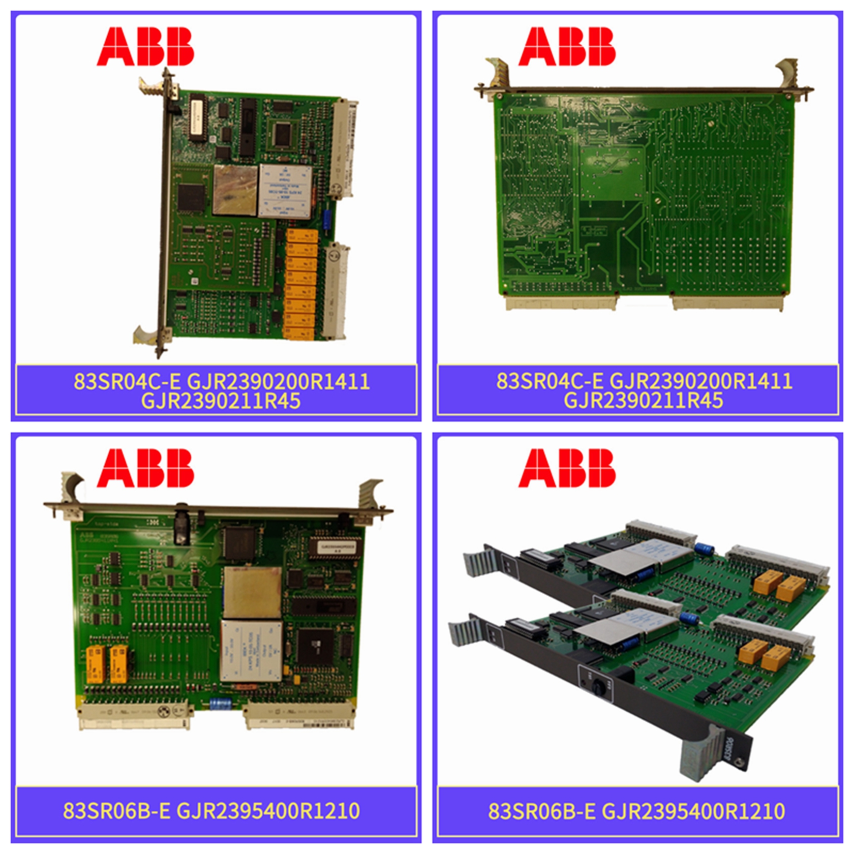
PFCL 201CE-20.0输出卡件
,、导线尺寸、分支电路保护和断开装置。否则可能导致人身伤害和/或设备损坏。TB3 TB1 TB2电源接线板控制和信号接线控制接口选项控制和信号屏蔽端子TB1 TB3 TE框架A1-A4 TB1控制接口选项1336 PLUS-6.16-2001年9月控制逻辑接线和适配器2-3控制接口板跳线重要事项:如果正在安装控制接口板,必须移除J2引脚3和4以及17和18处的主控制板跳线,并选择正确的[输入模式]。如果卸下该板,则必须重新安装这些跳线,并且必须将[Input Mode]参数编程为“Status(1)”。图2.2跳线位置数字输入数字输入连接到TB3。输入模式选择通过首先将[InputMode]编程为所需控制方案(即2线、3线或Status),可以使用多种组合。然后可以通过编程[TB3 Term 22 Sel]至[TB3 Term 28 Sel]来配置剩余的输入。有关编程信息,请参阅PLUS II用户手册第6章中的数字I/O参数组。J2框架1 A1-A4 1参考第1–1页了解框架参考分类。JOG ESC SEL J11 J8 J13 1336 PLUS-6.16-2001年9月2-4控制逻辑接线和适配器图2.3数字I/O默认设置-TB3.19 20 21 22 23 24 26 27 28 29 30 1请参阅速度选择表。2如果选择了此模式,则可以在[Input status](输入状态)参数处读取所有输入的状态。但是,只有“停止/故障复位”和“启用”具有控制功能。3在驱动开始之前,必须存在这些输入(如有必要,请重新编程)。[Direction Mask]的4位0必须=1,以允许TB3方向改变/双极操作。5需要为[Input Mode]选择“2线”控制。6[TB3 Term 22]必须编程为“Run Reverse”(反向运行)!2线控制存在自动重启造成人身伤害的危险。双线控制使用保持的运行触点,作为运行(关闭)和停止(打开)设备。断开停止触点(端子20)将停止驱动。如果该触点重新闭合,任何故障都将被重置。如果仍然存在有效的启动命令,驱动器将重新启动。仅对NFPA79“欠电压保护”中概述的应用使用2线控制。如果还使用3线设备(即HIM),则按下HIM停止键也将停止驱动器。松开停止键将清除所有存在的故障,但如果不循环启动触点,驱动器将无法重新启动。输入模式(仅限启动/停止功能)状态2(出厂默认值)状态停止/故障重置3 2线控制单电源控制正向运行停止/故障复位3 3线控制单源反向启动停止/故障恢复3通用Rev/For4(可编程)出厂默认输入2线控制示例3线控制示例点动(可编程[输入模式]时,右侧显示的(可编程的)速度选择21(可编程)速度选择11(可编程设置)通用启用3(不可编程)状态仅默认模式未激活
conductor sizes, branch circuit protection and disconnect devices. Failure to do so may result in personal injury and/or equipment damage. TB3 TB1 TB2 Power Terminal Block Control & Signal Wiring Control Interface Option Control & Signal Shield Terminals TB1 TB2 TB3 TE Frames A1-A4 TB1 Control Interface Option 1336 PLUS - 6.16 - September, 2001 Control Logic Wiring and Adapters 2-3 Control Interface Board Jumpers IMPORTANT: If the Control Interface Board is being installed, Main Control Board Jumpers at pins 3 & 4 and 17 & 18 of J2 must be removed and the proper [Input Mode] selected. If this board is removed, these jumpers must be reinstalled and the [Input Mode] parameter must be programmed to “Status (1).” Figure 2.2 Jumper Locations Digital Inputs Digital Inputs are connected at TB3. Input Mode Select A number of combinations are available by first programming [Input Mode] to the desired control scheme (i.e. 2 wire, 3 wire or Status). The remaining inputs can then be configured by programming [TB3 Term 22 Sel] through [TB3 Term 28 Sel]. Refer to the Digital I/O parameter group in Chapter 6 of the PLUS II User Manual for programming information. J2 Frames1 A1 - A4 1 Refer to page 1–1 for frame reference classifications. JOG ESC SEL J11 J8 J13 1336 PLUS - 6.16 - September, 2001 2-4 Control Logic Wiring and Adapters Figure 2.3 Digital I/O Default Settings - TB3. 19 20 21 22 23 24 25 26 27 28 29 30 1 See Speed Select Table. 2 If this mode is selected, the status of all inputs can be read at the [Input Status] parameter. However, only “Stop/Fault Reset” and “Enable” will have control function. 3 These inputs must be present (reprogram if necessary) before drive will start. 4 Bit 0 of [Direction Mask] must = 1 to allow TB3 direction change/bipolar operation. 5 Requires "2 Wire" control selection for [Input Mode]. 6 [TB3 Term 22] must be programmed to "Run Reverse." ! A hazard of personal injury from automatic restart exists with 2-wire control. 2-wire control uses maintained Run contacts that act as both Run (closed) and Stop (open) devices. Opening the Stop contact (terminal 20) will stop the drive. If this contact is reclosed, any fault will be reset. If a valid Start command is still present, the drive will restart. Only use 2-wire control for applications outlined in NFPA79, "Under Voltage Protection." If a 3-wire device (i.e. HIM) is also used, pressing the HIM Stop key will also stop the drive. Releasing the Stop key will clear any faults that are present, but the drive will not restart without cycling the Start contact. Input Mode (Start/Stop Functions Only) Status2 (Factory Default) Status Stop/Fault Reset3 2-Wire Control Single-Source Control Run Forward Stop/Fault Reset3 3-Wire Control Single-Source Reversing Start Stop/Fault Reset3 Common Rev/For4 (Programmable) Factory Default Inputs 2-Wire Control Example 3-Wire Control Example Jog (Programmable) Auxiliary3 (Programmable) Common Speed Select 31 (Programmable) Speed Select 21 (Programmable) Speed Select 11 (Programmable) Common Enable3 (Not Programmable) Status Only Default Mode shown at right is not active when [Input Mode]


