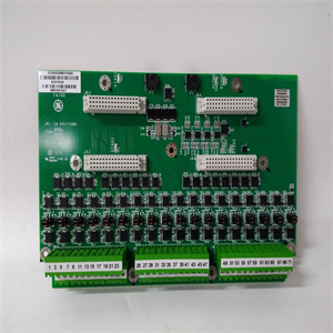
PFTL101B 3BSE004185R1系统备件
调试应由在安全安装方面有经验的训练有素的电气技术人员进行。需要以下专用工具:预绝缘对接接头的压接工具图21连接器(如Raychem AD-1522-T)图22热收缩用带反射器附件的热风枪(如Rayhem HL1802E)6.1 MAT INSTALLATION隔离并锁定机器电源。检查地板是否平整、光滑、干净、无碎屑,以及任何埋地管道或其他布线是否正确到位。拆开垫子,小心保持平整,不要拉扯电线。将垫子放置在地板上的计划位置,连接线位于检测区域的外围。根据图23将垫段连接在一起。图23注意:垫线具有黑色外层。两个具有黑色内护套,两个具有白色内护套(位置见图23)。控制单元1 2 3 4 26处的传感器垫白-黑-白-白-黑,黑-黑-黑,白-白,黑-白,白-黑端子留有足够的线尾长度,以便在更换垫的情况下重新制作连接,但确保互连电线能够轻松地安装在边缘装饰件下方,而不会被挤压。使用下图24所示的对接连接器连接电线。如果垫线需要延伸,例如前垫到后垫的连接和控制单元连接,则使用额外的一对对接连接器和一段双导线(参见布线规范-第6.2节)。图24组合修剪固定安装中使用的所有活动组合修剪部分必须斜接至45°。这有助于安装,并有助于保持传感区域的整体灵敏度。图24a周边饰板固定如果控制单元的接线未埋置,则在电线入口和出口位置切割周边饰板,并切割饰板坡度以适合所选导管系统。小心完全开槽,以便周边装饰件的任何弯曲都不会夹住电线。确保没有可能损坏导线的锐边或毛刺。图25进入电缆槽(周边饰板底部)的垫线建议切口的饰板固定件详图440F-T3013铝内角周边饰板(与440F-T3510、440F-T3310和440F-T3210一起使用)440F-T3012铝外部
Commissioning should be undertaken by a trained electrical technician experienced in safety installations. The following special tools are required: Crimp tool for pre-insulated butt splice Fig. 21 connectors (e.g. Raychem AD-1522-T) Fig. 22 Hot air gun with reflector attachment for heat shrinking (e.g. Raychem HL1802E) 6.1 MAT INSTALLATION Isolate and lock off the machine power supply at source. Check that the floor is flat, smooth, clean and free of debris and that any buried conduit or other wiring provision is correctly in place. Unpack the mats being careful to keep them flat and not to pull on the wires. Place the mats on the floor in the planned positions with the connecting wires at the periphery of the detection zone. Connect the mat sections together according to fig. 23. Fig. 23 NOTE: The mat wires have a black outer covering. Two have a black inner sheath and two have a white inner sheath (see fig. 23 for positions). SENSOR MATS WHITE BLACK WHITE WHITE BLACK BLACK WHITE BLACK WHITE BLACK WHITE BLACK TERMINALS AT CONTROL UNIT 1 2 3 4 26 Leave sufficient wire tail length to enable the connection to be remade if a mat is to be replaced, but ensure that the interconnecting wires will fit easily under the edge trim without crushing. Join the wires using butt connectors supplied as shown in Fig. 24 below. Where mat wires require extending, e.g. front mat to rear mat connections, and control unit connections, use an extra pair of the butt connectors and a length of twin wire (see wiring specification - section 6.2). Fig. 24 UNITING TRIM FIXING All active uniting trim sections used in installation must be mitred to 45°. This aids in installation and helps retain overall sensitivity of the sensing area. Fig. 24a PERIMETER TRIM FIXING Where the wiring to the control unit is not buried, notch the perimeter trim at the wire entry and exit positions and cut the trim slope to suit the conduit system selected. Take care to notch completely so that any flexing of the perimeter trim will not trap the wiring. Ensure that there are no sharp edges or burrs which could damage the wires. Fig. 25 Details of trim fixings SUGGESTED CUT-OUT FOR MAT WIRES ENTERING CABLE TRUNK (BASE OF PERIMETER TRIM) SUGGESTED CUT-OUT FOR FLEXIBLE CONDUIT ENTRY 440F-T3013 Aluminium internal corner perimeter trim (Use with 440F-T3510, 440F-T3310 & 440F-T3210) 440F-T3012 Aluminium external


