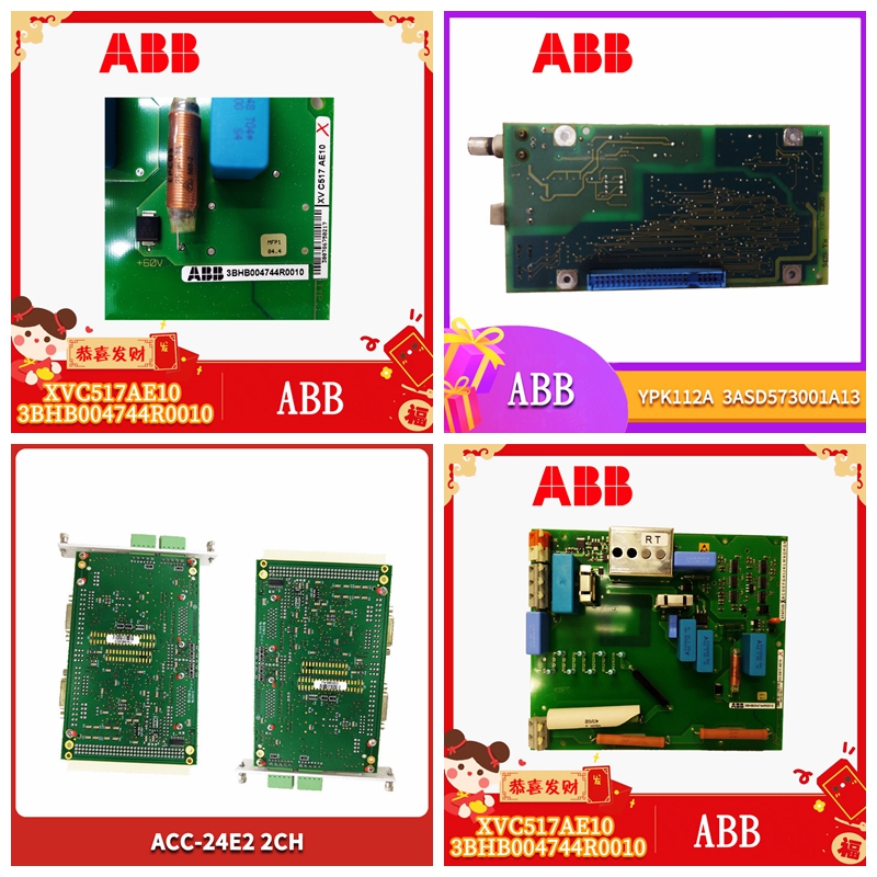
PFTL201D 50.0KN控制器模块
至控制单元时间驱动力控制单元安全输出功率至控制单元35 ms响应时间罗克韦尔自动化出版物95302194/EO:0240发行号:8 25 440F MatGuard™ Mat Manager用户手册第5节-安装设计将保持“关闭”状态,直到通电后复位,并且在存在其他通电联锁(启动联锁)的复杂系统中可能需要主/从复位电路。自动复位模式在自动复位模式下,输出“ON”信号仅通过移除驱动力实现。对于这两种模式,在启动垫子后,安全触点将始终处于“OFF”(断开)状态。当在自动复位模式下使用时,机器的控制系统将需要一个单独的复位功能,以防止机器在离开垫子或临时电源故障或跌落后启动。选择电源Allen-Bradley Guardmaster MatGuard Mat Manager控制单元为电源提供两种可能性。检查电源参数是否符合规范中给出的Allen-Bradley Guardmaster系统的要求。如果使用24V直流电源,则必须根据国际电气安全惯例(IEC 364-4-41)将其与主电源隔离。一个极应接地(直流电源负极接地)。辅助输出这是作为状态输出提供的非安全输出。它在使用PLC功能机器控制和硬接线安全电路作为PLC状态输入的系统中特别有用。其他用途包括保护方案中的诊断和/或驱动状态灯或警报。安全功能不得依赖于此输出。电弧抑制建议所有感应负载使用电弧抑制网络或设备。对于安全电路,抑制器应安装在负载上,而不能安装在触点上。抑制器的类型和额定值将由电源和负载特性决定。注意,抑制器可以增加响应时间,特别是直流线圈两端的抑制器二极管,并且在测量响应时间时应安装到位。5.8最终传感器垫布局考虑到这些因素后,现在可以检查并最终确定传感器垫布局。考虑机器响应时间是否与初始计算有所不同。在可能的情况下,应在检测区的外侧边缘设置垫子和电线。这简化了安装和更换(如果需要),并且所有布线都受到周边装饰的保护。5.9布线所有Allen-Bradley Guardmaster布线必须受到保护,避免机械损坏,并适当密封,以适应操作环境。提供防水对接接头用于垫子到垫子的连接,并由边缘镶边保护。如果需要穿过地板铺设电线,
to Control Unit Time Actuating Force Control Unit Safety Outputs Power to Control Unit 35 ms Response Time Time Rockwell Automation Publication 95302194/EO:0240 Issue No: 8 25 440F MatGuard™ Mat Manager User Manual Section 5 - Installation Design will remain “OFF” until reset after power up and may require master/slave reset circuits in complex systems where other power up interlocks (start interlocks) are present. Auto Reset Mode In auto reset mode the output “ON” signal is achieved solely by removal of the actuating force. For both modes, the safety contacts will always be “OFF” (open) after the mat is actuated. When used in the auto reset mode, the machine’s control system will need a separate reset function to prevent machine start up when stepping off the mat or after a temporary power supply failure or dip. Selecting the Power Supply The Allen-Bradley Guardmaster MatGuard Mat Manager control units offer two possibilities for power supply. Check that the power supply parameters conform to the requirements of Allen-Bradley Guardmaster system as given in the specification. Where a 24V DC supply is used it must be isolated from the mains supply in accordance with international electrical safety practice (IEC 364- 4-41). One pole should be earthed (negative to be earthed for DC supplies). Auxiliary Output This is a non-safety output provided as a status output. It is particularly useful in systems using PLC functional machine control in combination with hard wired safety circuits as a status import to the PLC. Other uses include diagnostics in protection schemes and/ or driving status lamps or alarms. The safety function must not depend on this output. Arc Suppression Arc suppression networks or devices are recommended for all inductive loads. For safety circuits, suppressors should be fitted across the load and never across the contacts. The type and ratings of the suppressors will be determined by the supply and load characteristics. Note that suppressors can increase response time, particularly suppressor diodes across DC coils, and should be in place when measuring response times. 5.8 Final Sensor Mat Layout Having considered these factors, the sensor mat layout can now be checked and finalized. Consider whether the machine response time has changed from the initial calculations. Whenever possible, mats should be arranged with the wires at the outside edge of the detection zone. This simplifies installation and replacement if required and all wiring is protected by the perimeter trim. 5.9 Wiring All Allen-Bradley Guardmaster wiring must be protected from mechanical damage and suitably sealed for the operating environment. Waterproof butt connectors are supplied for mat to mat connections and are protected by the edge trim. Where wire runs are required across the floor,


